
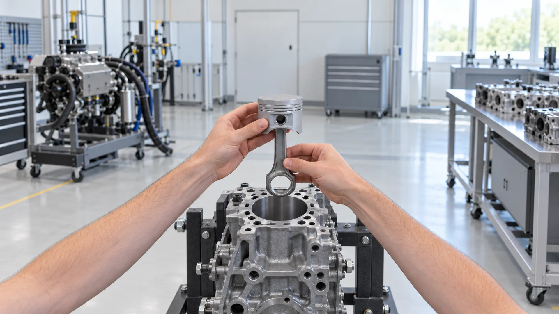
These prototype engine parts started with machining drawings: inch dimensions, tight fits and wrought aluminium or hot-rolled steel in the material field. We printed the shapes in DMLS aluminium and stainless steel, then machined the grooves and threads that needed tighter tolerances. An intake fitting used FDM ULTEM 9085 instead of aluminium.
This case study follows what changes when a machining drawing becomes a print order. Four of the eight designs came with drawings, which name a forging alloy, 6061-T6 and hot-rolled steel and say nothing about build direction, supports or heat treatment. The other four arrived as 3D models only.
The Project at a Glance
- Application: prototype engine hardware
- Parts: pistons and screw-in counterweights, a valve plate, two versions of a small valve head, valve seal protectors, a trigger wheel and an intake fitting
- Processes: DMLS in aluminium (AlSi10Mg for the pistons), 316L and 17-4 PH; FDM in ULTEM 9085
- Part definition: four inch-unit machining drawings calling for 2618 aluminium, 6061-T6 and hot-rolled steel; four parts defined by 3D model
- Post-print work: ring-groove machining to an agreed ±0.002 in (about ±0.05 mm) band, threads cut after printing and a sub-millimetre slit planned for wire EDM
- Production: small lots, with a design revision introduced between builds without tooling
- Delivery: seal protectors in 10 business days, 5 ahead of the promised date; pistons and counterweights in 13, on the date
A Small Engine, Drawn for the Machine Shop
Together the parts describe a small reciprocating engine. The piston is about 30 mm across, with a domed crown, three ring grooves and a blind threaded bore. A short counterweight screws into that bore and adds a mass set on its drawing. A thin valve plate the diameter of the piston carries seated ports, and small disc valve heads, about the size of a fingernail, each have a short central boss. A small domed cup with a tapped boss protects a valve seal.
The trigger wheel is a split-clamp hub with points around its rim; parts like this typically clamp to a shaft and pass a sensor to time an event such as ignition. The intake fitting is a flanged bell about 100 mm across, with several angled ports at its narrow end.
Process ChoiceWhy Print Parts That Were Drawn for Machining
The designs were ordered in small lots, so machining from bar would mean a separate setup, workholding and tool paths for very few parts, and several shapes are awkward to hold: fingernail-sized discs, a thin plate with conical seats, a hub with a slit under an overhang. A DMLS build needs supports but no fixtures or feature-by-feature programming, and those shapes come straight from the file.
What printing cannot do on its own is finish. As built, a DMLS part has a textured surface and a process tolerance measured in tenths of a millimetre, which cannot hold a ring-groove width, give a sliding finish or form a fine thread that assembles cleanly. So the route for most of these parts was print, then machine, the approach our hybrid manufacturing page describes: build the shape, then machine only the few features on each part that carry a fit.
MaterialsWhat the Drawings Specified, and What Was Printed
A drawing's material field records a decision about strength, temperature, mass or corrosion. These drawings name wrought grades and hot-rolled steel, the stock a machine shop cuts, so printing meant making each decision again. The printed material for each part was chosen as its quote was configured, so the order, not the drawing, carried the material decision. Before a design moves toward production, update the material field to match what is built.
| Part | Drawing called for | Printed in | What to check |
|---|---|---|---|
| Piston | 2618 aluminium or a better equivalent | DMLS AlSi10Mg | Strength at crown temperature, not room-temperature data |
| Counterweight | Hot-rolled steel | DMLS 316L | Mass: similar density, so it carries over |
| Trigger wheel | A36 hot-rolled steel | DMLS aluminium | Hub stiffness and clamp load in a lighter, less stiff alloy |
| Intake fitting | 6061-T6 aluminium | FDM ULTEM 9085, black | Strength across the layers and heat near the engine |
| Valve plate, first valve heads | No drawing | DMLS 316L | The 3D model is the definition |
| Seal protectors, revised valve heads | No drawing | DMLS 17-4 PH | Which heat-treated condition to specify |
From a forging alloy to a casting alloy
2618 is a wrought aluminium alloy of copper, magnesium and nickel, used for forged pistons because it holds its strength at elevated temperature, and the drawing allowed an equivalent or better alloy. AlSi10Mg is a casting alloy (EN AC-43000). EOS describes as-built DMLS AlSi10Mg as similar to T6 heat-treated cast parts and reports about 99.85% relative density. As built it is anisotropic: EOS gives 466 MPa ultimate strength, 233 MPa yield and 6.3% elongation vertically, against 461 MPa, 270 MPa and 10.2% horizontally. EOS's T6 treatment brings the two directions within about 5% of each other, but ultimate strength falls to 310 to 320 MPa as elongation rises to 11%.
Those are room-temperature results. A piston crown runs hot, and strength at temperature is the usual reason to specify 2618, so check that property before calling a printed alloy equivalent. On a development engine the substitution may be acceptable, but it is a judgement about temperatures and loads that belongs in writing against the drawing.
Steel to stainless, aluminium to polymer
The counterweight's 316L weighs about the same as its drawn hot-rolled steel, so the designed mass carries over. As a material, EOS reports about 100% relative density for its 316L, with as-built properties that meet ASTM A403, a wrought stainless fittings standard, without solution annealing.
The intake fitting, drawn in 6061-T6, was ordered in black ULTEM 9085 by FDM, at solid infill. Our 6061-T6 data lists 310 MPa ultimate strength. Stratasys gives ULTEM 9085 69 MPa in the XZ orientation and 42 MPa in ZX, where the load runs across the layers. Stratasys also lists a heat deflection temperature of 170 °C at 264 psi and UL 94 V-0 at 1.5 and 3 mm, material ratings that support a customer's own certification. A swap like this suits low-load parts only, checked against the weakest-direction figure.
The lines a bar-stock drawing leaves out
Drawings that name a wrought alloy rarely carry a heat-treatment line, because bar arrives in a known condition. A printed part starts as built, so when you order these alloys, write down the condition you want. EOS gives AlSi10Mg a stress relief of 90 minutes at 270 °C, after which it reports 310 MPa tensile strength, 200 MPa yield and 9% elongation. For 17-4 PH, EOS states that solution annealing and ageing are necessary for proper hardness and mechanical properties; after solution annealing and H900 ageing it reports 1,360 MPa ultimate strength in both build directions. HIP is available on DMLS where internal porosity matters.
TolerancesThe Title Block Still Applies
A machining title block sets a default tolerance for every dimension without its own. These drawings use a common inch block, with three-place decimals at ±0.005 in (about ±0.13 mm). Our DMLS tolerance is ±0.3% with a ±0.3 mm minimum, and on parts this small the minimum governs: about ±0.012 in, more than twice the title-block value. Read literally, the title block asks for machining on every three-place dimension.
The piston drawing asks for more still: a cylindricity control and a surface texture finer than 1 µm Ra on the outside diameter. Our AlSi10Mg data lists 6 to 10 µm Ra as built, so on a printed part a finish like that comes from a machining or polishing step, which has to be quoted like any other operation. Three habits follow:
- Declare which features carry the tolerance. Mark the surfaces that need machining-class limits; our drawing reconciliation review flags tolerance callouts tighter than the process standard before you order.
- Agree the inspection band before the order. The piston quote set a ±0.002 in acceptance band for the ring grooves before the order was placed. Every piston was then measured at eight features, including the three groove widths and three groove root diameters, and every reading was inside the band.
- Sample as-printed parts at process tolerance. The valve plate and first valve heads had no drawing, so a sample from each lot was measured against the model at ±0.3 mm, and every reading passed.
Print the Body, Machine the Interfaces
A ring groove's width sets the ring's side clearance and its root diameter sets how deep the ring sits, so drawings tolerance both in thousandths of an inch. As-built DMLS cannot hold that, and a groove left as printed would keep the textured surface on its walls. The piston quote therefore added a machining operation for the grooves after printing, with an agreed ±0.002 in acceptance band written in.
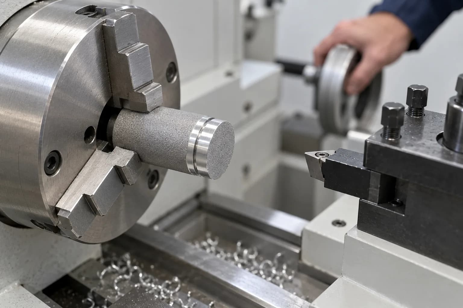
Print the body, then machine the features that carry a fit, such as ring grooves, sliding diameters and threads.
| Feature | Route | Why |
|---|---|---|
| Piston ring grooves | Machining after printing, to an agreed ±0.002 in band | Width and root diameter set the ring fit |
| Piston and counterweight threads | Both cut after printing | A fine-pitch thread shared by two mating parts |
| Seal protector thread | Bottom-tapped M6 after printing | A blind hole that needs thread close to its bottom |
| Trigger wheel slit | Planned on the order: printed closed, then cut open by wire EDM | Supports inside a sub-millimetre gap would be hard to remove |
| Valve plate and first valve heads | Printed as modelled, sampled at ±0.3 mm | No drawing; the model defines them |
Model the Tap Drill, Cut the Thread
None of the threads on these parts were printed, and the models were already set up for that. The piston's bore is modelled at the tap-drill diameter for its fine metric thread, drill-point cone included. The counterweight's thread is a plain cylinder at the major diameter, and the other tapped holes are modelled at tap-drill size. That is ordinary cosmetic-thread practice in CAD, and it suits a print-then-thread route: the hole is the tap's pilot, the cylinder is the die's blank, and the thread is cut into sound material.
Our DMLS design guide recommends printed threads only at M6 and above, warns that printed threads wear with repeated assembly and asks for holes sized for tapping with enough material around them. Even above that size, a fine-pitch thread that has to mate with another part is better cut. Both halves of the piston-to-counterweight joint were ordered with threading after printing, so the pair is threaded the way a machined pair would be. The seal protector's note asked for a bottom-tapped M6 thread in a blind hole, which calls for a bottoming tap; leave enough depth below the last full thread for the tap's point and the chips.
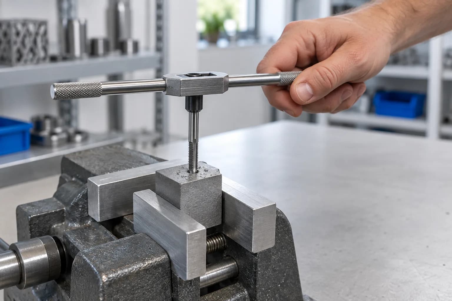
The printed hole is modelled at tap-drill size, and the thread is cut into it after printing.
A Slit Too Narrow to Support
The trigger wheel's clamp has a slit under a millimetre wide beneath an overhanging section of the hub. Our DMLS design guide puts the minimum gap at 0.5 mm, so the width alone is printable. The overhang is the problem: a downward-facing surface needs support structures to anchor it and carry heat into the build plate, and supports inside a gap that narrow are difficult or impossible to remove. After the order was placed, a machining line added to it set out the alternative: print the overhang with added material that closes the gap, then cut the gap by wire EDM and tap the clamp-screw hole as a standard post-machining step.
Wire EDM cuts a narrow, straight-walled slot with no cutting force, so a thin printed section is not pushed out of position while it is cut. The wire enters from an open edge or a start hole, so model the closed gap where the wire can reach it and leave the final width to the cut.
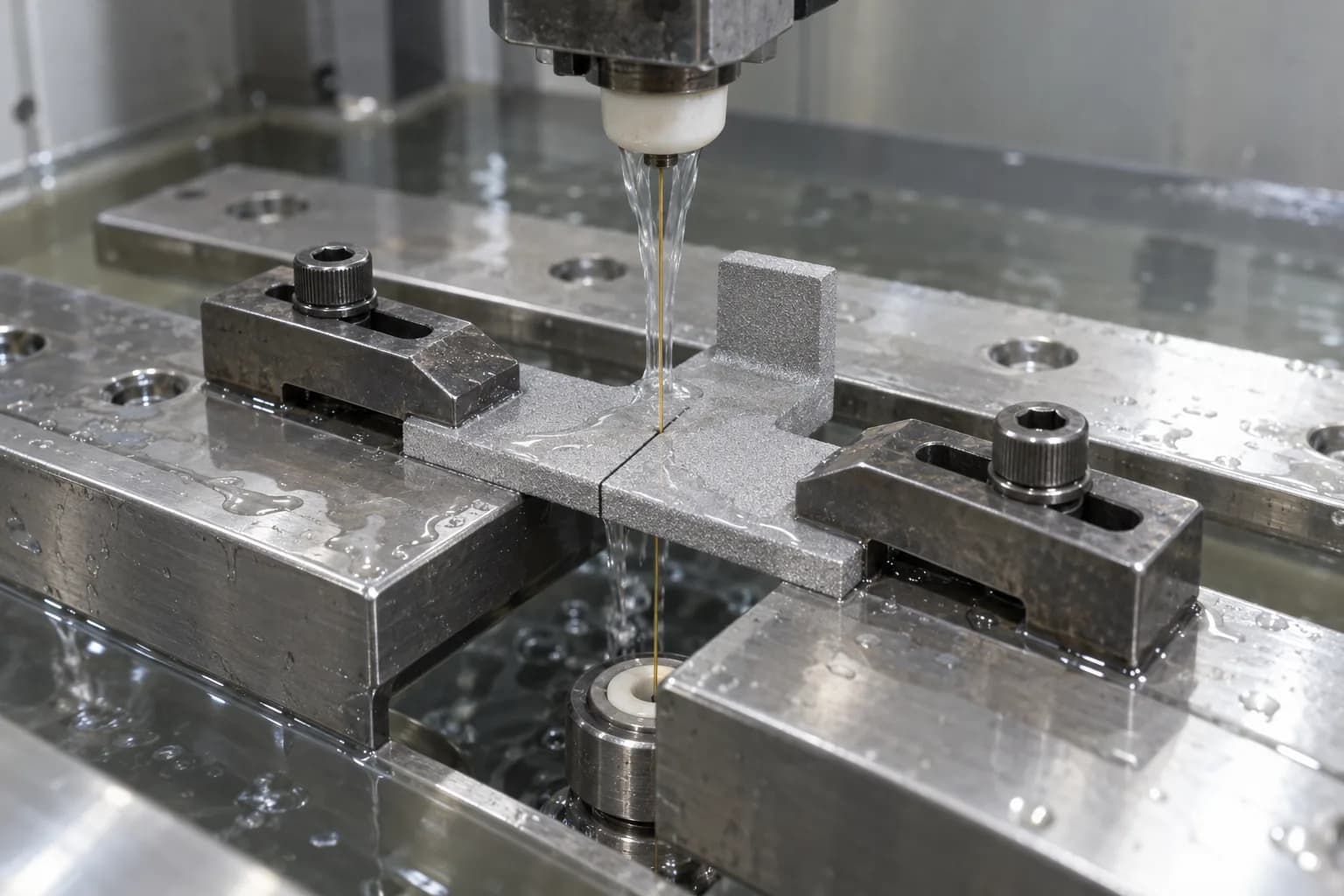
A gap too narrow to support during printing is printed closed and cut open afterwards by wire EDM.
Small Valve Parts and One Revision Between Lots
The valve plate and first valve heads were the simplest parts, printed in 316L as modelled, with conical seats, countersunk holes and flats straight from the file. The valve head was revised for a later order. In its first design the central boss is a small tube whose wall is under half a millimetre thick, below both the 1.0 mm supported-wall and 1.2 mm unsupported-wall minimums in our DMLS design guide. The revision replaces the tube with a solid pin about 2 mm across on a filleted collar, above the guide's 1.5 mm minimum pin diameter, and the reorder moved the part from 316L to 17-4 PH and added a machined thread. The records do not say why the customer made the change, but the new geometry is the sturdier one to print.
Renders barely tell the two versions apart: the bounding boxes are identical and the volumes differ by about half a percent, but the surface area drops about 5% as the tube and its bore become a pin. The same check caught real changes in our cab HVAC duct and enclosure case study.
ProductionHow the Orders Ran
Most orders followed the same path. The customer uploaded 3D files, with drawings where it had them, and configured material, quantity and post-print operations in our online quote, sending quotes for review where needed; staff entered some lines after review. During review and order handling the drawing callouts became line items: thread cutting with the thread specified, groove machining with its acceptance band and the wire-EDM plan. The piston measurements and the as-printed samples were recorded before those lots shipped.
Two of the lots show what a print-then-finish schedule can look like. The 17-4 PH valve seal protectors, tapped after printing, shipped 10 business days after the order, 5 ahead of the promised date. The pistons and counterweights, with groove machining, threads on both parts and every piston measured, shipped 13 business days after the order, on the promised date. On a print-then-finish route the finishing steps are part of the lead time, so put them on the quote from the start.
OutcomeDelivery and Results
- Eight designs in two processes: DMLS aluminium, 316L and 17-4 PH, plus FDM ULTEM 9085.
- Precision features finished after printing: every piston measured at eight features, all inside the agreed ±0.002 in band, and threads cut on both parts of a threaded pair.
- Two lots on or ahead of the promised date: seal protectors in 10 business days, 5 early; pistons and counterweights in 13, on the date.
- A revision as a file change: a valve head redesigned from a hollow tube to a solid pin and moved to 17-4 PH, then ordered in a larger lot with no tooling.
What to Apply to Your Own Machined-to-Printed Parts
- Decide the material again; do not translate it. A material field records a reason. Find the property that justified the drawn alloy, and check the printed one against it.
- Define "equivalent" in numbers. Write down the properties and temperatures that define it; room-temperature data may not settle it for a hot part.
- Add the lines a bar-stock drawing leaves out. State the heat-treatment condition, any build-direction constraint and the surfaces to be machined, and update the material field.
- Split each drawing into print-as-is and machine-after features. Mark the few surfaces that carry a fit, and let the model govern the rest at process tolerance.
- Agree the inspection band at the quote. Put each machined feature's tolerance on the quote, and measure those features on every part.
- Model the tap drill, cut the thread. Cut fine-pitch and mating threads after printing, even above the design guide's M6 minimum for printed threads, and write "bottom-tapped" when a blind thread must run deep.
- Print narrow gaps closed and cut them open. A gap that would need support inside it is better opened by wire EDM.
- Keep small features above the design-guide minimums. In DMLS: 1.0 mm supported walls, 1.2 mm unsupported walls and 1.5 mm pins; a thin-walled tube is a candidate for a solid pin.
- Check polymer substitutes in their weakest direction. Compare FDM strength across the layers, not along them.
Could Your Engine or Test-Rig Parts Be Printed?
Good candidates are metal parts for engines, compressors, pumps and test rigs that are needed in small lots and change between builds: pistons and weights, valve plates, small covers, brackets and sensor targets. They print well when most of their shape can live with process tolerance and only a few features need machining. Parts where nearly every surface carries a machining tolerance are usually still better cut from bar, as our comparison of CNC machining and 3D printing explains.
Match the alloy to the job rather than to the old drawing: AlSi10Mg for light parts that would otherwise be cast, 316L for corrosion-resistant parts and 17-4 PH for hardness and strength once solution annealed and aged. For polymer parts near heat, see our comparison of ULTEM 1010 and ULTEM 9085.
For more energy applications, see 3D printing for energy and clean tech and our case studies on touch-proof high-voltage covers in MJF PA12, threaded flange fittings in clear SLA and SLS PA12 and hairpin stator assembly nests in SLS PA12.
Have Machining Drawings for Parts You Want Printed?
Send us the drawings, the 3D files and the quantities. We will recommend a process and material for each part and put the features that need machining after printing on the quote. Lead times start at 2 business days, 24-hour turnaround is available on request, and we offer next day shipping anywhere in the US and Canada.
Discuss Your Parts With Us