
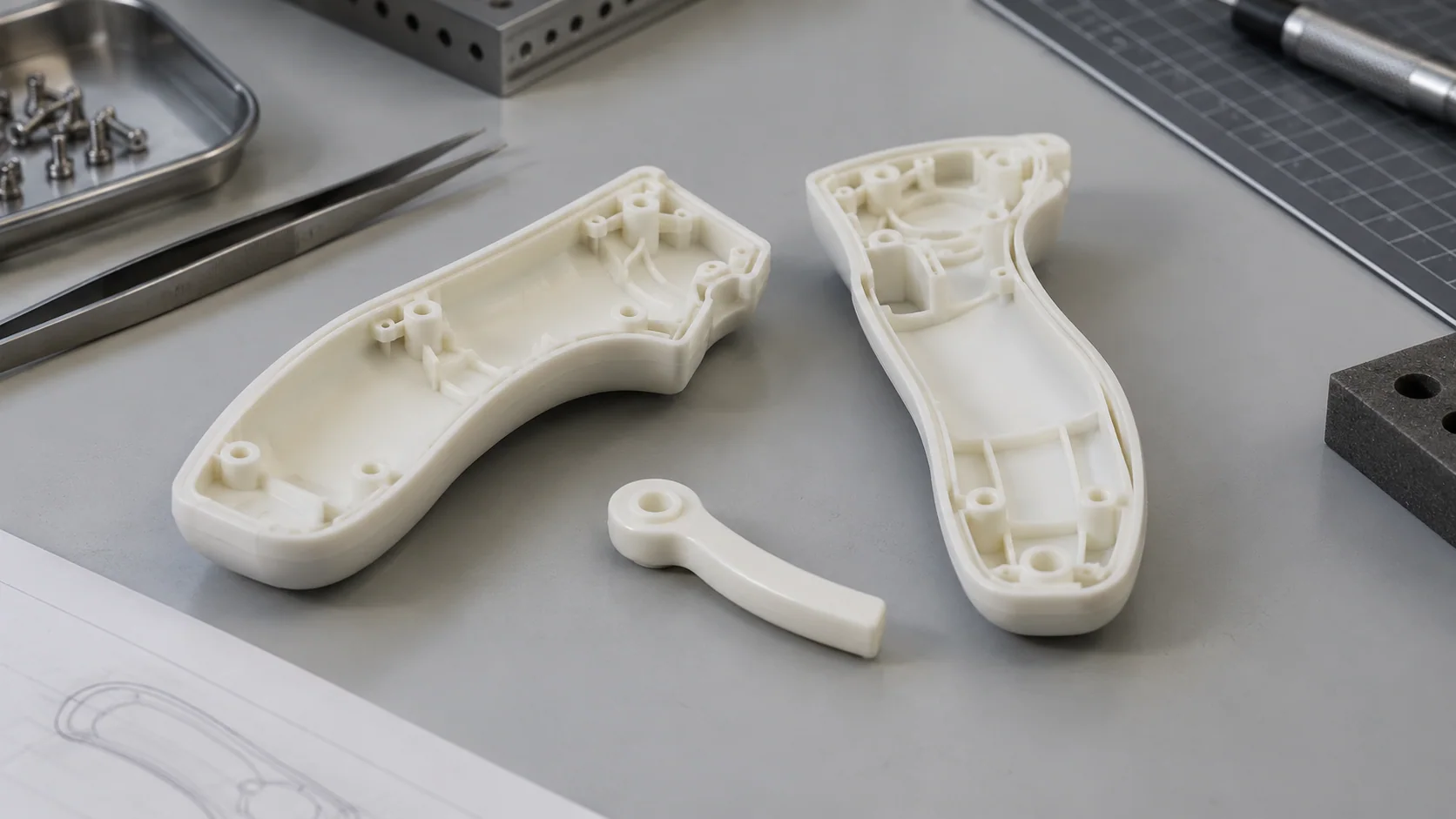
A medical device housing has to feel right in the hand while keeping everything inside it in place. The curve of a grip, the clearance around a lever and the way two shells close together all become easier to evaluate once the design is a physical part.
Forge Labs manufactured SLA handle shells and small mechanism components for medical device development, alongside separate SLS nylon casing designs. The work ranged from a few assembly samples to batches of dozens of parts. Each example brings a different manufacturing decision into focus: a smooth surface for handling, enough flexibility for a retaining feature, or a controlled first print before the rest of a batch.
The Work at a Glance
- Parts: paired handle shells, compact enclosure halves and small internal mechanism components
- Materials: SLA Accura 25 and ClearVue, plus SLS PA12 for separate casing designs
- Engineering focus: mating edges, mounting features, thin walls and retaining clips
- Demonstrated turnaround: a nylon casing batch shipped in about one working week, including an initial pair printed ahead of the balance
- Result: manufactured evaluation parts and small batches without mould tooling
Use the Prototype to Resolve the Whole Assembly
The handle designs combined a curved grip with openings for controls and space for the mechanism inside. We made left and right shells, together with components such as levers, wheels and stops. Producing the surrounding parts as well as the outer housing gives a design team the pieces needed to check how the assembly comes together.
That is where Stereolithography (SLA) is particularly useful. Its fine detail and smooth surfaces reproduce subtle changes in contour, rim geometry and control openings. A designer can assess the grip and reach of a control while also checking whether the halves meet cleanly. Small changes to the CAD model can go straight into another print, keeping the design open while these decisions are still being made.
Accura 25 gives a handle shell a firm surface with some compliance during assembly. Its polypropylene-like behaviour suits functional prototypes and snap-fit assemblies: a thin feature can give as the parts engage, while the surrounding shell holds its shape. The practical benefit is a prototype that can be handled and assembled while the team evaluates the geometry.
We also produced handle shells in ClearVue. A clear version adds another way to examine an assembly: internal contact points and moving-part clearances become easier to see through the wall. For this kind of review, surface finishing can concentrate on the viewing area that answers the design question, keeping the prototype useful and the finishing work focused.
Assembly FitGive Mating Features Room to Work
The important geometry lives where parts meet. A shell rim sets the seam, a boss supports a fastener, and a bore or recess locates a moving component. Those relationships deserve attention together. An attractive outer surface contributes little if tightening the housing traps a lever or pulls the two halves out of alignment.
Our SLA design guide gives a standard tolerance of ±0.25%, with a ±0.25 mm minimum for parts within the standard size range. On a small mating feature, that minimum matters. A pin and its hole both vary, so the fit needs enough allowance for the two manufactured parts to come together. The useful dimension is the assembled clearance, considered alongside each part's tolerance.
For a housing, the CAD model defines the shape and a drawing can identify the few relationships that control assembly: the spacing between fixing points, a pivot diameter or the gap around a moving lever. Concentrating the requirements there helps preserve the design intent through printing and finishing. It also makes dimensional inspection more useful than treating every outer surface as equally critical.
Small geometry changes can make a large difference to the feel of a housing. A lead-in helps one half locate inside the other. A rounded boss root spreads the load from a fastener into the wall. A rib adds stiffness across an open panel while leaving room for the mechanism. These features can be built into the same print, allowing the assembly to be refined without adding separate brackets or spacers.
Make Small Clips Strong Enough to Handle
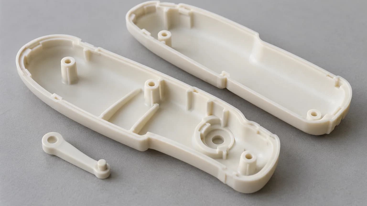
A separate casing design used SLS PA12. The compact shells contained mounting bosses, an open internal cavity and retaining features around the edge. Nylon combines low weight with toughness and useful flexibility, giving a handled enclosure some resilience during assembly. Its behaviour also suits clips that need to move out of the way briefly as two parts engage.
Selective Laser Sintering (SLS) builds these features within a bed of powder, which supports the geometry as the laser forms the part. There are no attached support structures to remove from the inside of the shell. Open cavities, bosses and retaining features can therefore be arranged around the assembly, with access left for cleaning out the loose powder.
Our review identified very thin areas and fine edges at the clip tips. We discussed which details mattered to the evaluation, then printed an initial pair before producing the remaining shells. This gave the shop a physical check on the delicate geometry before committing the balance of the batch.
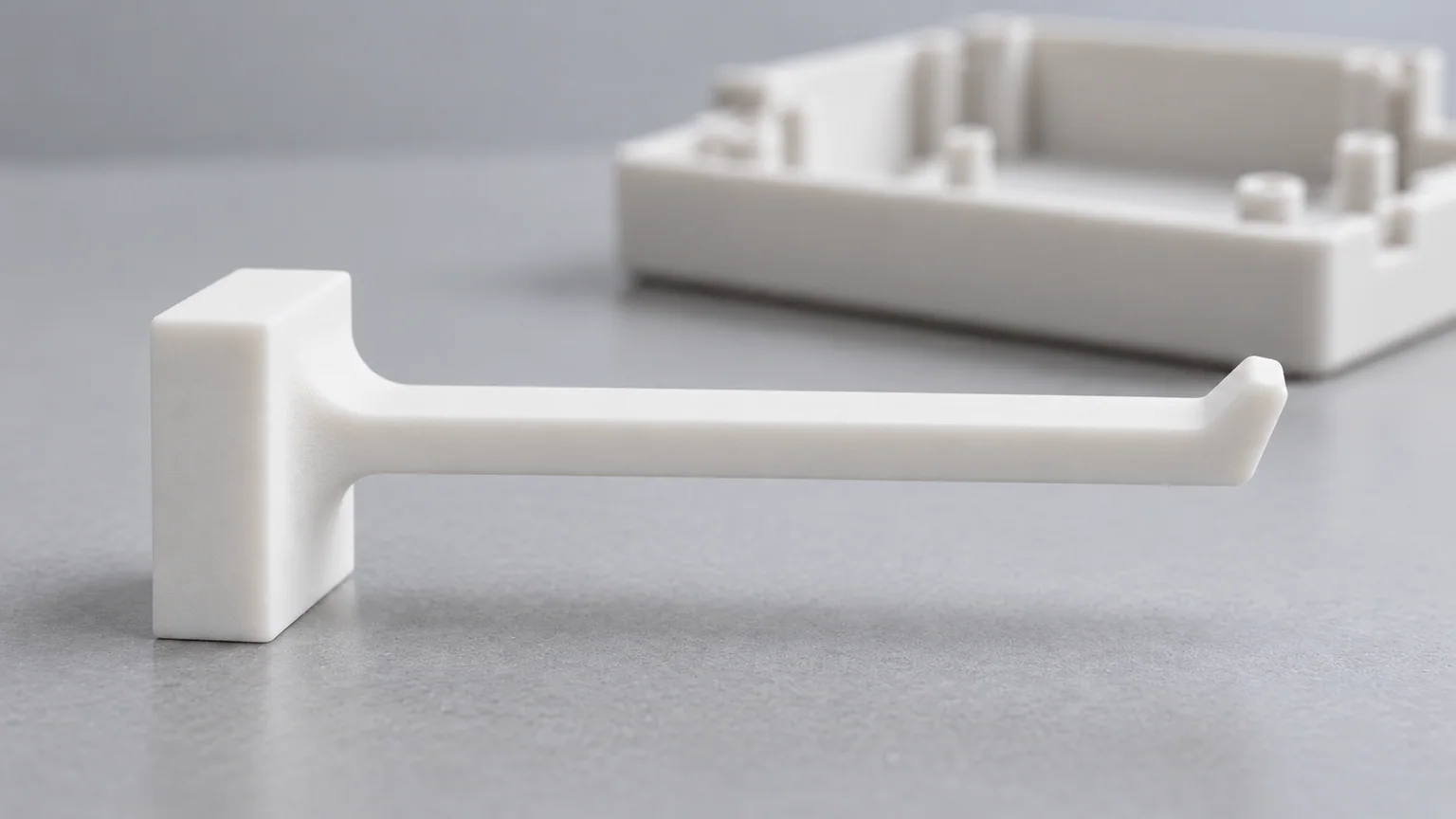
The SLS design guide starts supported walls at 0.8 mm, with thicker sections needed where a wall stands freely. A clip also needs enough length to flex and a rounded root that spreads bending into the surrounding wall. Keeping the lead-in smooth helps it slide into position, and allowing space behind the clip gives it somewhere to move. These choices improve both assembly and the part's ability to survive cleaning and handling.
Plan the Finished Part From the Start
For an SLA housing, preparation begins with the orientation and support locations. We consider the outer grip, the mating rim and the small internal features together so finishing can reach the supports while preserving the surfaces that matter. Printing is followed by cleaning, support removal and UV post-curing, with local finishing at the attachment points.
The SLS route starts with arranging the shells in the powder bed. After printing and cooling, the parts are unpacked, depowdered and bead blasted. Thin clips need care during this stage as well as in the printer. In the casing review, we considered whether those features would benefit from more controlled manual finishing. Planning for that handling early helps a delicate prototype reach the assembly bench with its useful details intact.
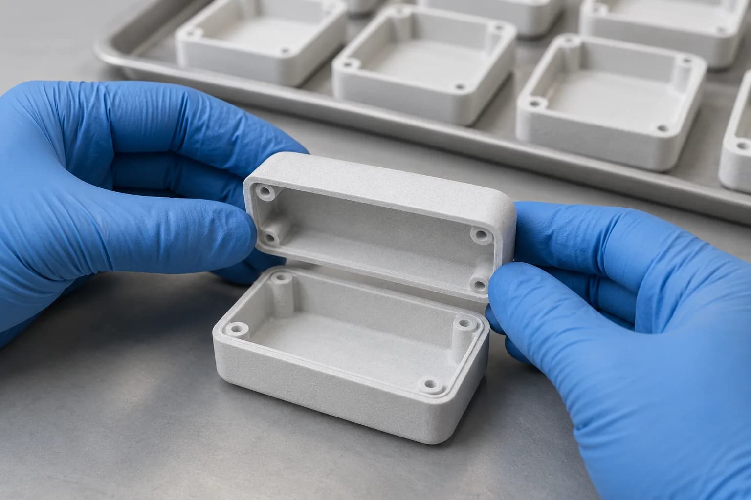
The initial nylon pair and subsequent production builds were completed on industrial EOS machines. The batch of dozens of shell components shipped in about one working week from order submission. That interval included the first print check and the work needed to finish the parts. It demonstrates how a small production batch can incorporate a manufacturing check while keeping the turnaround practical for development.
Batch size can follow the work the customer needs to do. A few sets support early assembly checks; a larger group gives a team more parts for parallel evaluation. Additive manufacturing allows that choice without investing in a mould, and a change to a clip or control opening can be incorporated into the next requested revision.
Useful InspectionCheck the Features That Determine Fit
A first pair is especially useful when two shells must agree. It allows the seam, fixing positions and retaining features to be examined together, including details that are awkward to judge from separate CAD views. For a handle assembly, a simple fit check with the internal hardware can reveal where clearance needs adjusting before more parts are made.
First article inspection can also be selected when configuring parts in our portal. It provides a focused dimensional check against the agreed requirements before a larger batch proceeds. For a housing, its value is confidence in the features that locate the assembly and let it operate: a pivot seat, a fastener pattern or a mating rim.
Forge inspects every medical part, with cleanroom post-processing and packaging. Keeping the material, CAD revision and finishing requirements together also makes subsequent parts easier to compare with the samples already evaluated. The portal retains the part configuration and order history, so teams can reorder an established design or submit its next revision with the manufacturing context in place.
Keep the Design Moving With Parts You Can Assemble
These jobs delivered physical handles, housings and mechanism components for medical device development. SLA brought smooth contours and detailed assembly features into the evaluation parts. SLS made compact nylon casings with integrated retaining and mounting geometry, supported by an initial print check before the larger batch.
The useful lesson is to choose the prototype around the decision it needs to support. Surface feel, visibility into the assembly, clip movement and dimensional fit each point toward a material and a manufacturing approach. Bringing those choices together turns medical device 3D printing into a practical way to develop and manufacture the parts surrounding the technology inside.
Developing a Medical Device Housing?
We can review your handle or enclosure geometry, select materials for the evaluation you need, and plan the finishing and inspection around its assembly features.
Discuss Your Parts