
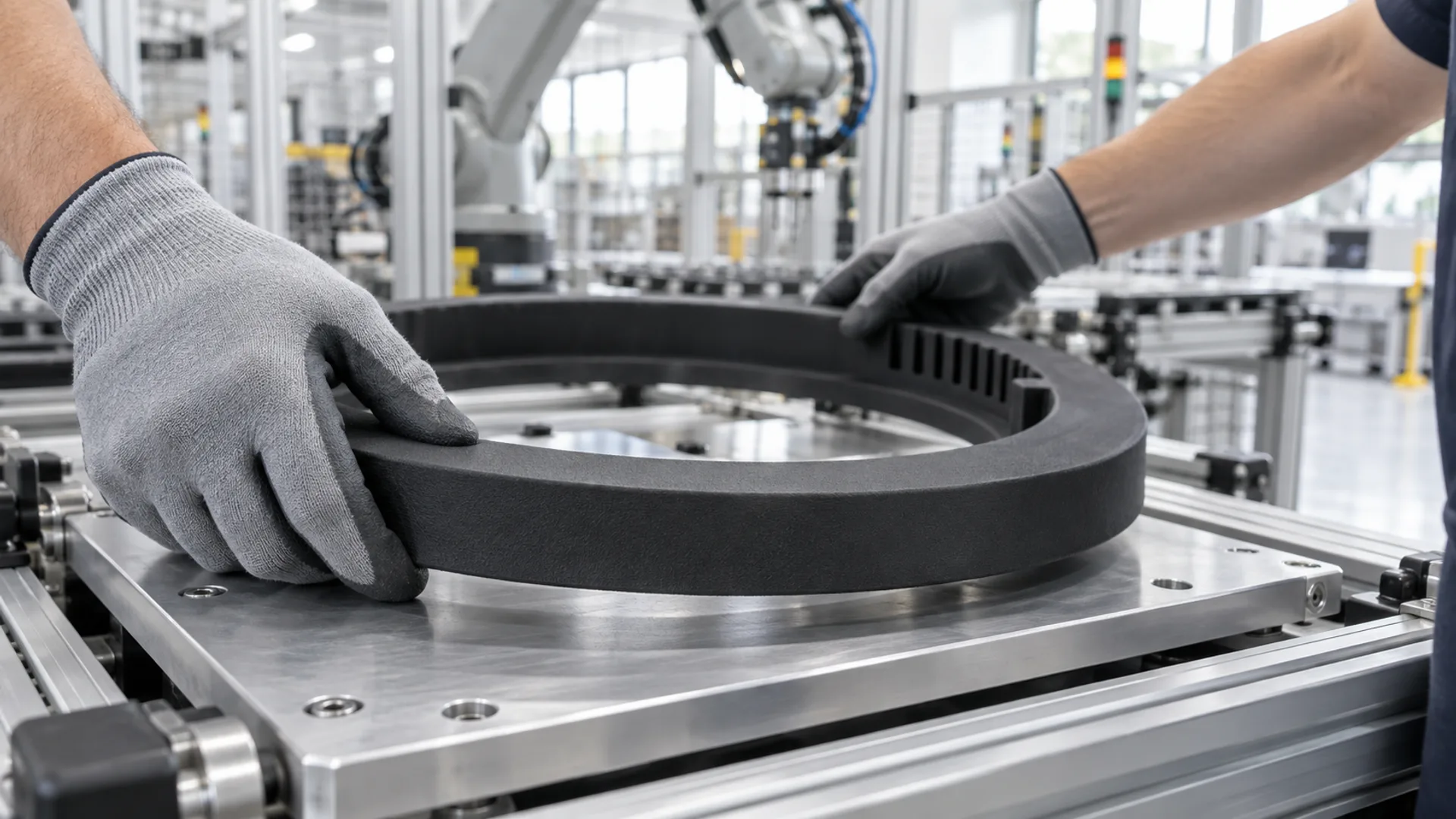
These slotted assembly nests needed a non-marring surface and a slot pattern that would be costly to machine. We printed them in SLS nylon and dyed them black in-house. Flexible snap-in tray inserts used FDM TPU after a process change during quote review. These examples show how geometry, handling and production volume guide the choice of process and material.
Line tooling can range from a few dedicated fixtures at each station to production batches of tray inserts. The useful question is what each part needs to do: hold a precise pattern, protect a contact surface or flex repeatedly without losing its grip.
Process and Material at a Glance
- Rigid assembly nests: SLS PA12 nylon for deep slots, low weight and non-marring contact surfaces, with an in-house dyed-black finish.
- Flexible tray inserts: FDM TPU for snap-in retention and soft contact, at a lower unit cost for this geometry.
- Design priorities: slot clearance and powder removal for nests; infill, print orientation and retention for flexible inserts.
- Production planning: scale from station tooling to batches of hundreds, with staged shipments when parts are needed before the full run is complete.
Two Fixtures Built Around One Slot Pattern
The nests use a disc and sleeve with a shared pattern of narrow slots. Their geometry illustrates the main challenge in this type of tooling: keeping many closely spaced positions aligned while leaving enough clearance for loading and unloading.
What a nest does in hairpin stator assembly
Hairpin stators use flat, insulated copper bent into U-shaped pins to form the motor winding. In a typical basket assembly process, the hairpins are arranged in their winding pattern before being inserted together into the stator's insulated slots. Their exposed ends are then twisted and joined.
An assembly nest holds components in position during assembly or transfer. For hairpin stator tooling, the slot count, layer radii and spacing follow the winding layout. This helps explain the repeated slots in these fixtures—and why a different stator design can require a different nest.
The disc has narrow radial slots; the hollow sleeve has deep internal slots. They share the same slot count and inner slot radius, forming a matched pair. Thin ribs separate the slots, while mounting and locating features position the fixtures at the station.
Small pin-style tools can complement a nest as guides, locating keys or checking tools. Their exact function depends on the station; the design lesson is to consider these supporting tools alongside the main fixture.
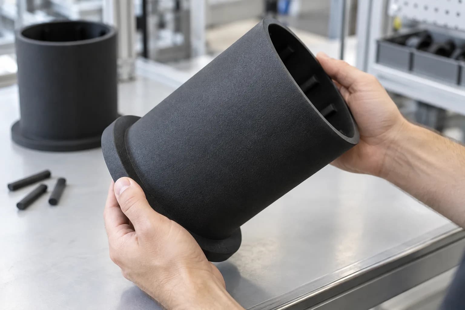
Deep internal slots that would need long-reach machining or EDM are built in the same pass as the rest of an SLS part.
Why SLS Suits Slotted Nests
The slots are the expensive part to machine
The disc's slots are open from the face and could be milled, but dozens of deep, narrow slots mean long slender cutters, many passes and thin ribs that deflect under the cut. The sleeve's slots are internal and closed at one end, which calls for long-reach slotting, broaching or EDM, or splitting the part. SLS price follows the volume sintered and the space a part takes in the build, not its feature count. Each slot removes material, so the slots themselves add little to the build cost. The cost they do add is in depowdering: deep, narrow, blind slots hold unsintered powder and take longer to clear than a plain tube.
Lead-ins and undercuts come free
On the disc, the rib tops taper so each slot is wider at its entry than at its root. That lead-in guides components into place. On a machined fixture it is an extra operation repeated on every slot; in a printed one it is just geometry, so model it. Unsintered powder also supports the part during the build, so the sleeve's internal shoulder and the pins' cross holes need no support structures.
Design the slots and ribs for the process
A slotted nest pushes several SLS limits at once, and the time to respect them is in CAD:
- Keep ribs above the minimum wall. Our SLS design guide sets 0.8 mm for supported walls and 1.5 mm for unsupported ones. A rib that tapers to a lead-in should stay above that at its tip, or the tip will be fragile and may not fully form.
- Leave room for powder to escape. Narrow gaps can fuse shut or trap powder, and the same guide gives minimum gap sizes against wall thickness. Where slots are blind, open the closed end or add an exit path if the function allows it, so powder can be blown or brushed out.
- Plan for flatness on large flat parts. Large flat planes are the SLS geometry most prone to warp. A 250 mm-class disc that must seat on a pallet should locate on bosses, pads or bores rather than relying on the whole face being flat, and a stepped or ribbed section is stiffer than a plain plate.
- Allow for moisture. PA12 is hygroscopic; our data lists 1.5% absorption in 24 hours. The dimensional effect is small, but on a tight slot fit it is another reason to design clearance rather than line-to-line contact.
- Treat nests as consumables. Slot walls and lead-ins wear with every load. Because a replacement is a reprint of the same file, keeping a spare per station costs far less than stocking machined spares.
Light, insulating and gentle on parts
SLS PA12 is a tough, lightweight and electrically insulating nylon suited to repeatedly handled assembly tooling. Its softer contact surfaces help protect the insulation on copper hairpins during loading and removal. Smooth lead-ins and controlled slot clearance guide the conductors into position while reducing catching and scraping. PA12 also resists ethanol, isopropyl alcohol and hydraulic fluid, supporting routine cleaning and maintenance around the line.
A printed sleeve of this size weighs around a kilogram. The same geometry in aluminium would be nearly three times heavier; in acetal, about one and a half times heavier; in steel, roughly eight times heavier. Lower fixture weight makes manual changeovers easier and, on robot-mounted tooling, leaves more payload available for the parts being handled.
FinishBlack by Dyeing, Not Paint
SLS PA12 comes out of the machine white, and MJF PA12 comes out grey. The black on these nests, as on all our black SLS PA12 and MJF PA12 parts, is dyed, not painted, and we do the dyeing in-house on DyeMansion equipment. DyeMansion's DeepDye process puts the parts in a heated, pressurised water bath, where the dye reacts with the nylon itself instead of drying on top as a film. DyeMansion gives the penetration as up to about 0.2 mm into the open pores of the surface, depending on the material. That depth is why DyeMansion calls the finish more durable than spray paint: the colour is part of the surface, so there is no paint layer to chip off an edge or rub through where the part touches something.
On a nest that difference is practical rather than cosmetic. The rib tops and lead-ins are loaded and unloaded every cycle, which is exactly where a paint film would wear first, and paint flakes are the last thing an assembly cell wants near clean copper. Coating the walls of dozens of deep, narrow slots evenly with a spray gun is also difficult. Before dyeing, each part goes through the three steps DyeMansion builds its process around: it is cleaned of powder, bead-blasted to an even surface, then dyed. DyeMansion develops its colours for parts surfaced this way and matches its recipes to the base material and finish, so the black comes out the same from one run to the next. A spare nest printed months later should look like the ones already on the line.
Specifying colour on line tooling
- Ask for dyed black on parts that are handled. For SLS or MJF nylon, dyeing gives a colour with no film to chip, which suits fixtures, grippers and trays better than paint.
- Treat the colour as a surface layer, not solid colour. The dye reaches a fraction of a millimetre into the part. DyeMansion itself notes that lighter base material can show under mechanical stress where the dye layer is shallow, so a lead-in that wears hard over many months may lighten at its tip. On a fixture, that is a useful sign to check the slot and swap in a spare.
- Do not count on colour for wear resistance. DyeMansion's own testing found that the choice of dye has no effect on the material's scratch resistance. Size ribs and lead-ins for wear exactly as you would for undyed nylon.
- Put the colour in the part specification. When a reorder or a spare must sit beside parts already in service, name the colour on every order so each batch is made to the same finish.
Our surface finishes page covers dyeing alongside the other finishing options.
Build EnvelopeCheck the Envelope Before You Freeze the Design
Compact SLS machines typically have a bed around 200 × 250 mm. The disc is at the limit of such a bed and the sleeve is beyond it. Both were quoted on a large-format platform; our large-format PA12 build volume is 340 × 340 × 600 mm. Compare a fixture's bounding box with your supplier's envelopes while the design can still change; a part slightly over a limit can often be reoriented, trimmed or split. Our guide to splitting large parts covers joint placement.
Fit and ToleranceSlot Fit and First Article Inspection
Our standard SLS PA12 tolerance is ±0.3%, with a minimum of ±0.3 mm. That is about ±0.75 mm across a 250 mm fixture, while a narrow slot follows the ±0.3 mm minimum. Slot clearance deserves particular attention because it controls how easily the conductor loads and releases.
For a matched disc and sleeve, the critical dimensions are the slot widths, locating bores and the features that align the pair at the station. We can agree tolerances around these interfaces and the clearance the assembly needs. A shared slot layout in CAD keeps both fixtures coordinated as the winding design changes.
You can add first article inspection (FAI) when configuring your parts in our portal. Checking those critical dimensions against agreed tolerances helps catch dimensional issues early and gives you more confidence when ordering additional fixtures for the line.
Small Tools and ScheduleSmall Tools Can Share the Build
Small pins take almost no room alongside large fixtures, so they can usually fill spare space in a build, and SLS prints engraved numbers and cross holes in place, with no marking or drilling afterward. Keep engraved text at least 0.5 mm wide and deep so it does not fill with powder. Locating keys and insertion fingers can be produced alongside the nest, while checking tools are sized to the slot clearance and inspection requirements.
Specify the commissioning date and which tools are needed first when requesting a quote. If the line can start with a subset of fixtures, a staged shipment can get those stations ready while the remaining parts are produced.
The Tray InsertsFlexible Snap-In Inserts for Production Trays
Each insert is a hand-sized flexible ring. A thin flange carries a thin-walled locating collar around a central opening, and integral barbed snap pegs project from the back face. The pegs push through holes in a tray plate and lock, and the collar gives the component carried in the tray a soft, non-marring seat.
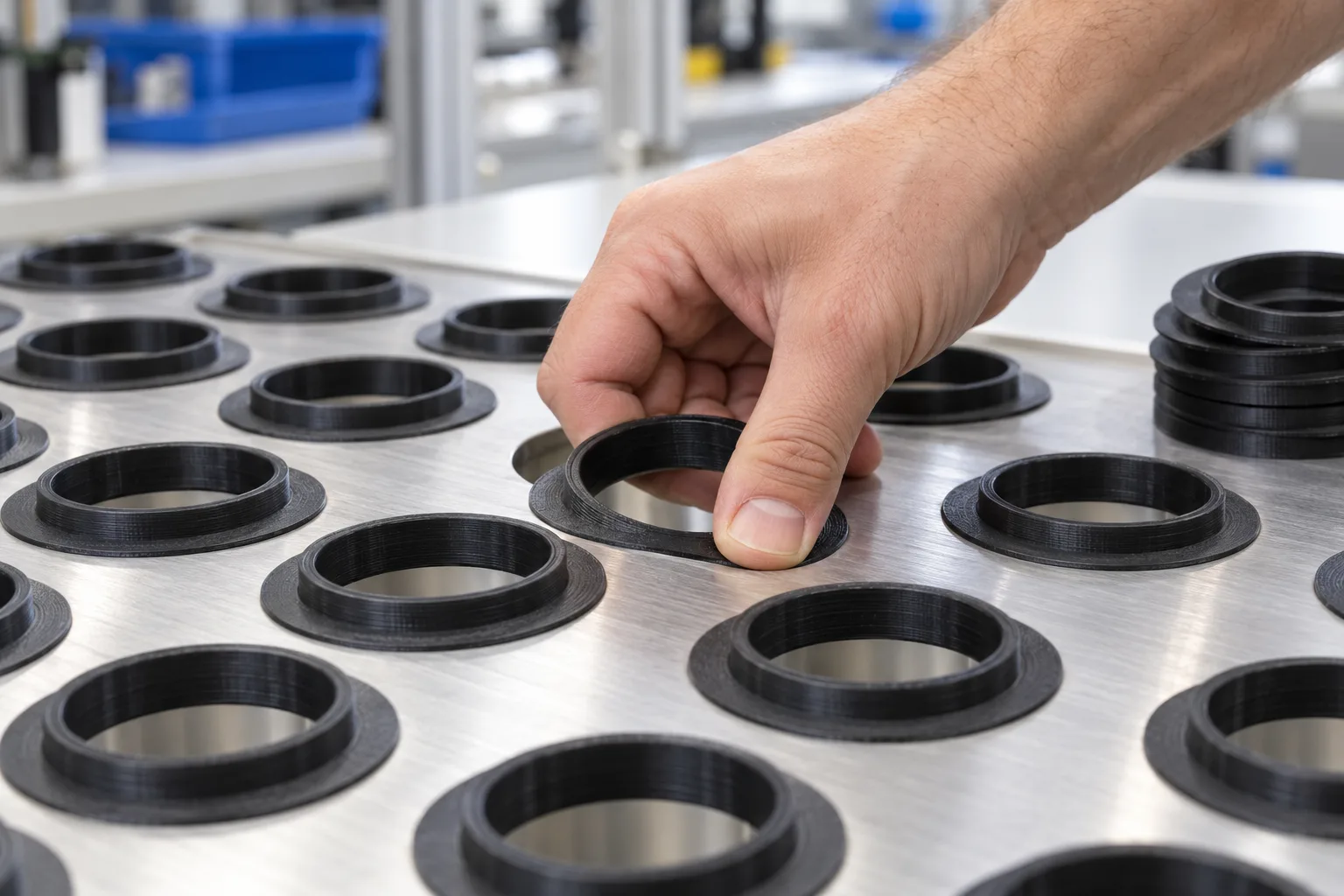
A soft TPU seat snaps into a plain hole in the tray plate, with no fasteners or adhesive.
Each barb compresses through its hole and springs back behind the plate, and the evenly spaced pegs centre the insert, so the tray needs only plain holes and no screws or adhesive. In a mould the barbs are undercuts, needing side actions, collapsible cores or a stripping design. For batches of hundreds, printing avoids that tooling and its lead time, and a change to the insert is a file change rather than a mould modification.
Elastomer Process ChoiceMoving From SLS TPU to FDM TPU During Review
The initial choice was SLS TPU 88A. Its Shore 88 to 90A hardness describes a firm, rubber-like feel: the seat can cushion contact while supporting the part in the tray. In testing along the printed layers, its 270% elongation at break means the sample stretched to 3.7 times its original length before breaking. That capacity to deform is useful for snap pegs that bend as they pass through a mounting hole.
The insert's flat flange, simple collar and short pegs also suited FDM. We proposed a black Shore 90A-class TPU with similar firmness, and the price came in noticeably lower per part. For this wide, low shape, filament printing provided a more economical way to make the geometry. SLS remains valuable for lattice cushions, complex internal shapes and parts where support-free surfaces matter.
Infill and OrientationInfill Is a Design Variable for Flexible Parts
The inserts used solid infill, but the right infill level depends on the balance between flexibility and retention. In an FDM elastomer part, infill sets how stiff the flange feels and how firmly each barb resists pulling back through its hole. Lower infill is cheaper and softer; solid gives the most consistent retention and wear life under repeated tray loading. Test retention at the infill you will order, because a peg qualified at one infill level will not behave the same at another. See our article on FDM infill for the trade-offs.
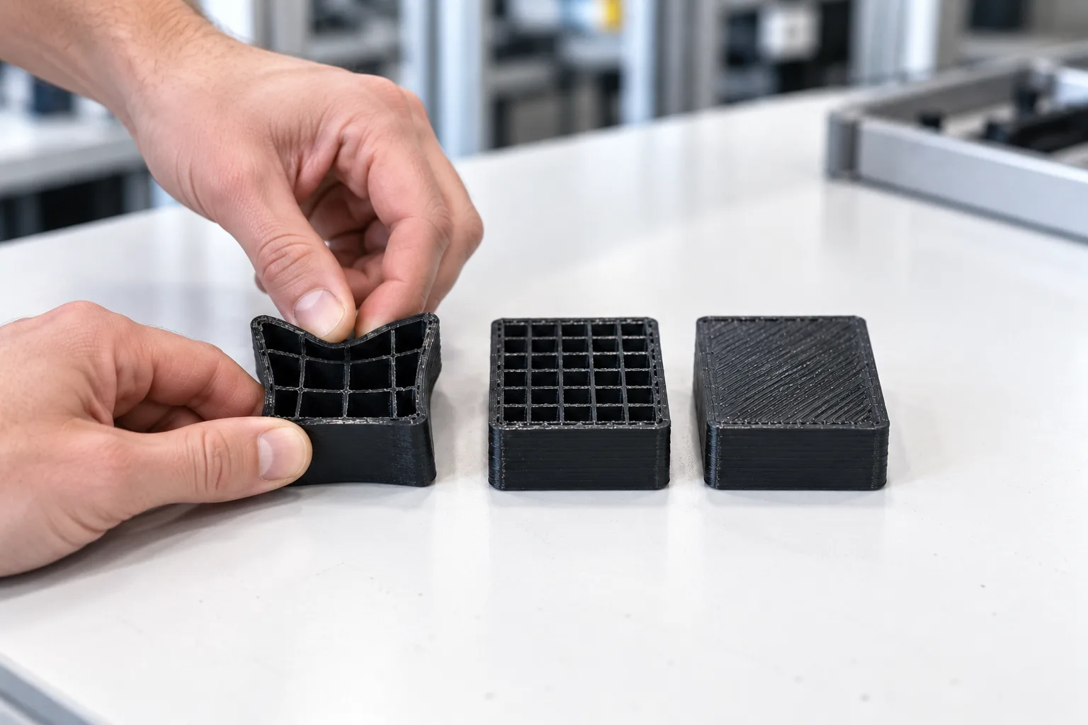
Sparse, medium and solid infill in the same elastomer give noticeably different stiffness and retention.
The insert has features on both faces: pegs on one side, a collar on the other. Any FDM orientation therefore needs supports under one set of features or a compromise in finish. Decide during design which face may carry support marks, and keep the seating surface clear of them. Orientation also decides peg strength. FDM parts are weakest across their layer lines, so a peg built along the vertical axis carries its pull-out load across the layer bonds. Either orient the pegs so retention is not loaded across layers, or qualify pull-out force on parts printed in the orientation you will order. Our guides to part orientation and supports cover the options.
Files and DeliveryPlanning a Production Run
For production batches, specify the material, infill, orientation and critical fits before the run begins. Keep part numbers and revision labels consistent, and identify any geometry changes when sending updated files. This gives the supplier a clear basis for producing and checking repeat parts.
The tray inserts demonstrate a run of hundreds of flexible parts, with initial shipments leaving in about a week and the full run shipping over roughly three weeks. Staged delivery can support line setup before every tray is ready. Timing depends on geometry, quantity and finishing, so agree the first-shipment and full-run dates when quoting.
OutcomeMatching the Process to the Tooling
- Complex rigid fixtures: SLS PA12 builds repeated slots and internal features without machining each one individually.
- A lower-cost flexible part: switching the tray inserts to FDM TPU reduced unit cost while retaining a Shore 90A-class elastomer.
- Production beyond prototypes: flexible inserts can be supplied in batches of hundreds, with staged deliveries supporting line setup.
| Decision | Slotted nests and pins | Snap-in tray inserts |
|---|---|---|
| Process | SLS, large-format bed | FDM |
| Material | Nylon PA12, dyed black | Shore 90A-class TPU, black |
| Design priority | Slot clearance, rib strength and powder removal | Snap retention, infill and print orientation |
| Why it suited the part | Dozens of deep, narrow slots (internal in the sleeve), size, low weight | Simple shape, elastomer, unit price |
What to Apply to Your Own Line Tooling
- Print the features that are expensive to machine. Deep, narrow or internal slots add little build cost in SLS, because price follows volume and build space. Leave a path for powder to clear.
- Model the lead-ins. A tapered slot entry guides parts in and costs nothing extra, as long as the rib tip stays above the minimum wall.
- Check the build envelope early. Fixtures in the 250 mm (10 in) class are at or beyond the limit of compact SLS beds.
- Confirm the critical dimensions. Design slot clearance around the SLS tolerance and use first article inspection to check the dimensions that control loading and alignment.
- Specify dyed colour on handled nylon tooling. Dye becomes part of the surface rather than a film that can chip, but it is a fraction of a millimetre deep and does not make the surface more scratch-resistant, so design for wear as usual.
- Compare processes for flexible parts. A simple flanged TPU part came in noticeably cheaper in FDM than in SLS.
- Treat infill and orientation as a specification. Qualify snap retention at the infill and orientation you will order.
- Specify the production run. Keep revisions clear, agree critical fits and request staged shipments when an initial batch can support line setup.
Could Your Line Tooling Be Printed?
Good candidates are needed in small numbers per station, are slow to machine or awkward to mould, and change with the product: nests, locating pins, gauges, end-of-arm fingers and tray inserts. Large rigid fixtures usually suit SLS PA12; soft-contact and snap-in parts suit TPU, by SLS or FDM depending on shape and quantity.
See 3D printing jigs and fixtures, 3D printing for automotive, and our case studies on SLA cab HVAC ducts and 400 mm SLS enclosures and repeat SLS PA12 production without tooling.
Building or Changing a Production Line?
Send us your fixture files, the quantity per station and your need date. We will recommend a process and material for each part and can split shipments so commissioning starts sooner. Lead times start at 2 business days, 24-hour turnaround is available on request, and we offer next day shipping anywhere in the US and Canada.
Discuss Your Fixtures With Us