
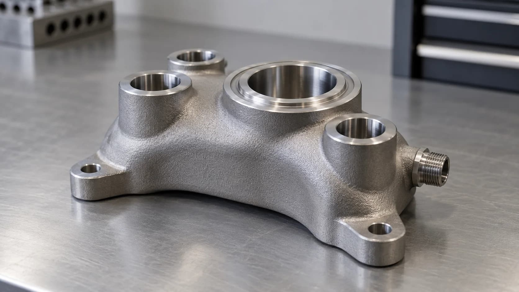
A maintenance fixture can look simple from the outside while carrying several jobs inside: guiding air to the right connection, positioning seals and giving a technician a secure grip. For this stainless steel test plate, Forge combined metal 3D printing with machining so the internal passages and precise interfaces could work together in one body.
The fixture was made for aircraft engine maintenance. Its design brought functions from several earlier tools into a consolidated handheld assembly, with internal air passages, threaded connections and replaceable O-ring seals. We manufactured the body in 316L stainless steel, then machined the features that control connection and fit. The useful lesson is in that division of work: print the geometry that benefits from additive, and plan the precision surfaces into the manufacturing route from the beginning.
The Project at a Glance
- Application: handheld air-test tooling for engine maintenance.
- Material and process: 316L stainless steel, manufactured by Direct Metal Laser Sintering (DMLS).
- Printed features: the fixture body and its connected internal air passages.
- Secondary work: machined holes, pipe and handle threads, O-ring grooves, and internal passage finishing.
- Delivered result: a printed and machined stainless body made to the customer's consolidated fixture design.
Bring the Air Path and the Connections Together
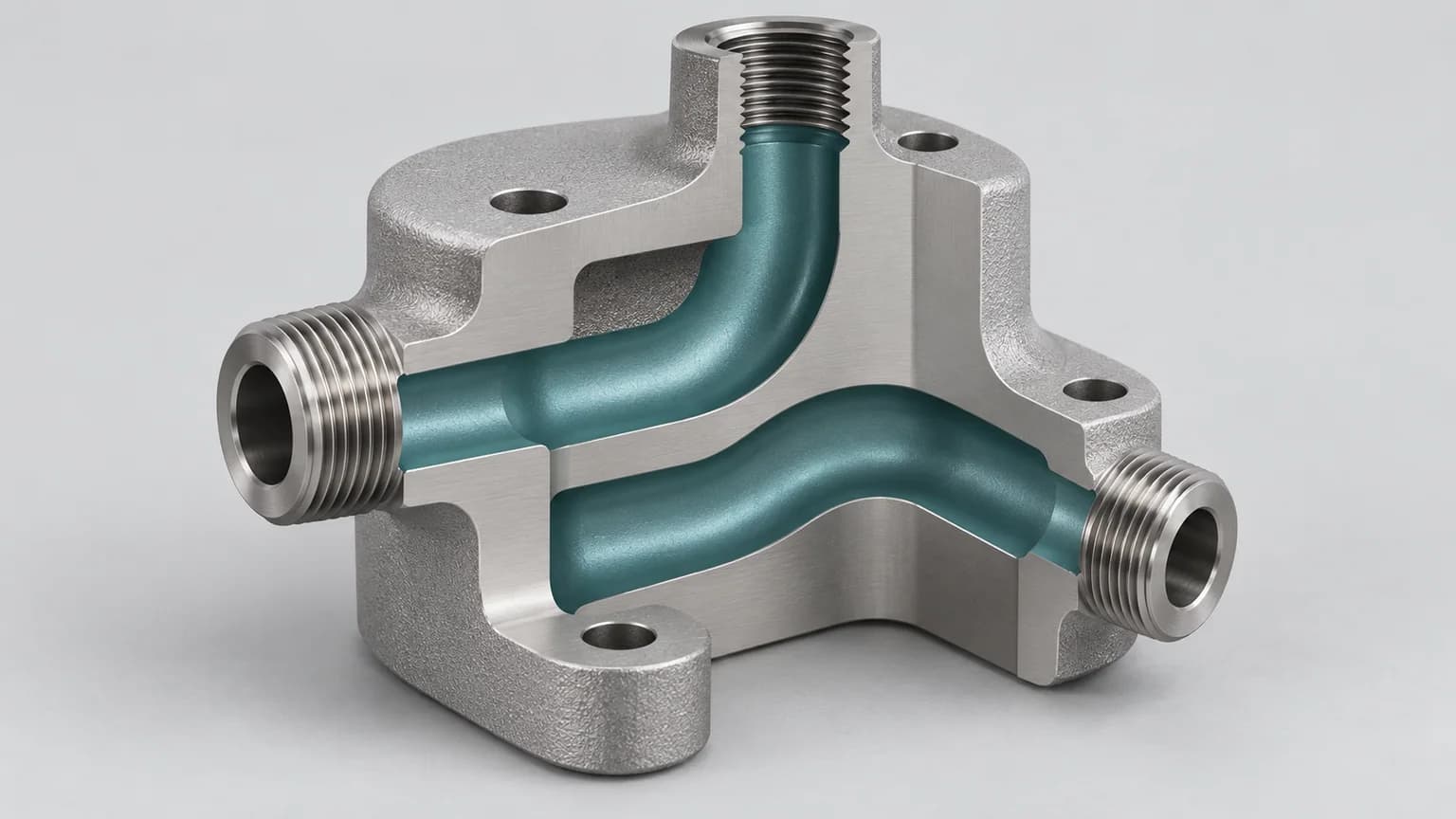
The outside of a test fixture follows the equipment it connects to. Ports need to meet their mating features, seals need room to compress, and the handle needs to leave the working area accessible. Inside, the air path connects those interfaces. Designing both together gives a compact tool a clear purpose: one body carries the air and locates the connections.
DMLS builds the metal body a layer at a time, allowing passage geometry to develop through the part. A conventional drilled passage follows the access available to the drill; intersecting routes can require additional openings and plugs. Additive gives the designer more freedom to place transitions inside the body and keep the external shape suited to handling and access.
Here, the customer had already combined the earlier tooling functions in the design. Forge's role was to manufacture that design with its internal geometry intact and its interfaces ready for the specified hardware. For similar fixtures, consolidation can reduce the number of separate bodies, connections and pieces that need to be aligned during assembly. The strongest candidates combine useful internal complexity with a relatively small number of accessible precision surfaces.
Stainless Steel for a Tool That Gets Handled
A handheld fixture needs stiffness around its sealing faces and enough material around its threads to carry tightening and handling loads. 316L provides a tough metal body that can be drilled, tapped and finished locally. Its corrosion resistance and toughness suit tooling that is handled, cleaned and returned to the bench between uses.
Those properties have practical consequences for the design. The body supports the ports as fittings are tightened, a solid threaded boss gives the handle a secure attachment, and the sealing regions can be machined to a smooth finish. Generous transitions between a boss and the surrounding body help spread the local load. The designer can put material where these connections need it while using the internal geometry to carry air through the tool.
The fixture used a natural metal finish. Finishing effort was concentrated on the areas that connect, seal or carry flow. Keeping those requirements local makes the drawing more useful: the machinist can see which surfaces need close attention, while the rest of the printed body retains its functional metal finish.
Drawing to ProductionLeave Material for the Features That Need Precision
The drawing package separated the printed shape from the finished machining requirements. Selected bores were deliberately undersized, leaving roughly 0.8 mm of diameter allowance for machining. Cutting them to their final size removes the printed surface and gives the tool a controlled hole diameter and location. An allowance stated on diameter is shared between the two sides of the bore; that distinction matters when preparing the print model.
This is a useful way to work with metal printing tolerances. The printed body establishes the overall shape, while secondary machining brings critical interfaces to the drawing. Allowance is chosen around the geometry, orientation and finishing operation so there is enough stock for a clean cut. Planning it in CAD also keeps adequate wall thickness around a port after the final hole has been opened up.
The machining scope included tapered pipe threads for the air connections, a straight thread for the handle, through holes and countersinks. Each feature serves a different purpose. Pipe threads establish the fitting connection; the handle thread transfers the operator's load into the body; clearance holes allow the specified hardware to fit. A drawing makes those distinctions clear and gives manufacturing a target for each operation.
For a new fixture, the most useful drawing information is close to the working features: thread specification and depth, finished bore size, sealing finish, and the surfaces used to locate the part during machining. A flat holding face or accessible boss can make the secondary operation much easier. Additive design includes how the printed body will be held for the next step.
Give Each O-Ring a Controlled Seat
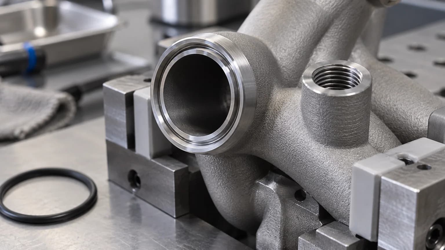
An O-ring seals by compressing against its mating surfaces. Groove depth controls that compression, while groove width leaves room for the rubber to change shape. A smooth contact face and rounded, clean edges help the seal sit correctly and avoid damage during assembly. These details turn a small ring of rubber into a dependable connection.
The fixture drawing defined the O-ring grooves in section, including local radii and separate surface-finish requirements. Some contact surfaces called for 32 microinches Ra, approximately 0.8 micrometres. Ra describes the average roughness of the surface: here, the fine finish matters because the seal bears directly against it. Machining those regions provides control over both the groove geometry and the surface the rubber touches.
O-ring gland design brings together seal size, compression, surface finish and the pressure direction. Applying that thinking early helps position the seal where it can be machined and inspected. It also makes replacement straightforward: the tool body carries a defined seat for standard hardware.
The internal passages received their own finishing scope. Surface texture and local restrictions affect how air moves through a channel, so passage size, transitions and access for finishing belong in the same review. An open, accessible route makes powder removal and cleaning easier. When the air path turns inside the part, those access points should be designed alongside the route itself.
Through the ShopPlan Printing and Machining as One Job
The production route combined a printed stainless body with the machining scope agreed from the drawings. After the successful print, the part moved through post-processing and machining before dispatch. The completed body shipped within three business days of the successful print being confirmed, covering the final finishing and machining stage.
For this type of work, turnaround is shaped by the whole route. Build preparation includes orientation, support placement and access to remove powder. Supports hold the metal geometry during printing and carry heat into the build plate. Their placement needs to work with the machined faces, internal openings and the way the body will be clamped afterward.
Planning the machining at the quoting stage lets those decisions support one another. Threads have enough surrounding stock, seal seats remain accessible, and finishing operations have a defined scope. Printing, support removal, machining, cleaning and inspection can then be scheduled around the completed tool. That is particularly useful for a maintenance fixture needed at a specific work station, where the fitting and sealing features determine whether the delivered part is ready for assembly.
A Manufacturing Route for Compact Maintenance Tooling
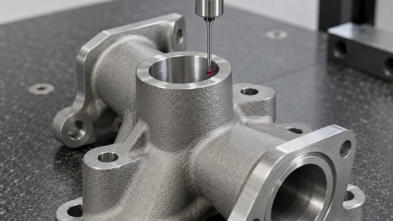
Forge supplied the consolidated fixture body in stainless steel, with its internal air paths printed and its connection features machined. The project shows how a detailed tool can move from a drawing package to a delivered metal part by assigning each feature to the process that serves it best.
The same approach applies to pneumatic test blocks, compact manifolds and other maintenance tools with internal routes and precision connections. Start with the interfaces the tool must meet, give the passages enough room for flow and cleaning, and plan machining stock around the surfaces that control fit. That combination makes additive manufacturing useful well beyond the first shape prototype.
Forge combines aerospace tooling experience, metal printing and secondary machining to manufacture these parts. Share your model and drawing with our team to review the internal geometry, finishing requirements and production route for your next fixture.