
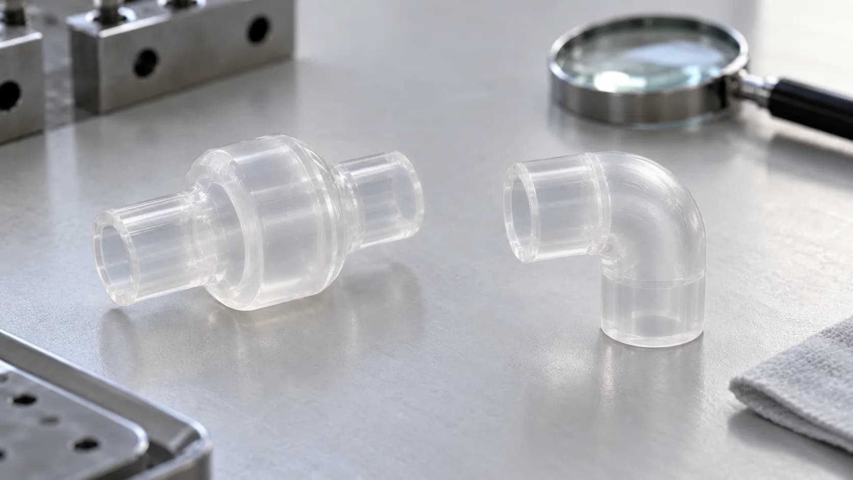
A fluid-handling assembly brings several design problems into a small space. Passages must remain open, connections must fit, and the parts around the tubing need to move comfortably and consistently. Additive manufacturing lets each component take the shape its job requires, with the material and finishing chosen around that function.
Forge manufactured two complementary types of medical-device hardware: transparent fluid bodies in Accura ClearVue, and separate pinch-valve bodies and hand knobs in SLS Nylon PA12. Both were supplied in batches of dozens. Their drawings reached beyond overall size to define passage checks, material grades, surface finishing and protected packaging. Those details made the difference between a printed shape and a component prepared for the next stage of assembly.
The Manufacturing at a Glance
- Parts: clear fluid bodies and separate nylon pinch-valve hardware
- Processes: SLA in Accura ClearVue and SLS in PA 2200 Nylon PA12
- Design focus: open passages, connector geometry, printed threads and comfortable hand controls
- Quality requirements: drawing-defined inspection, specified cleaning and material documentation
- Production: small batches manufactured directly from the supplied CAD models
See the Passage as Well as the Part
The clear components combined a hollow body, connection features and smaller passages within one printed form. Stereolithography builds these details by curing liquid resin with a laser. The process gives designers a way to bring curved walls, transitions and connection points together without first creating a mould for the surrounding shape.
ClearVue adds a useful view into that geometry. Its transparency and smooth surface finish suit fluid-visualisation models and transparent assemblies. During development, a clear body can help a team see whether an internal connection is seated, where liquid collects or whether a passage needs closer examination. That visibility makes a physical sample particularly valuable when the flow path is difficult to understand from the outside.
Clarity starts with the design and build setup. Broad viewing areas benefit from gentle wall transitions and support placement that leaves the important surface accessible. Around a hose connection, a rounded root spreads the load introduced when tubing is fitted. The useful question is what the designer needs to see or connect, then how the wall and port geometry can support that task.
For medical components, the finishing route belongs in this decision too. The clear-body order specified the USP Class VI ClearVue workflow, including its cleaning requirements. Viewing quality, contact requirements and any proposed surface treatment are reviewed together so the finished sample serves the intended evaluation.
Check the Features That Make the Part Work
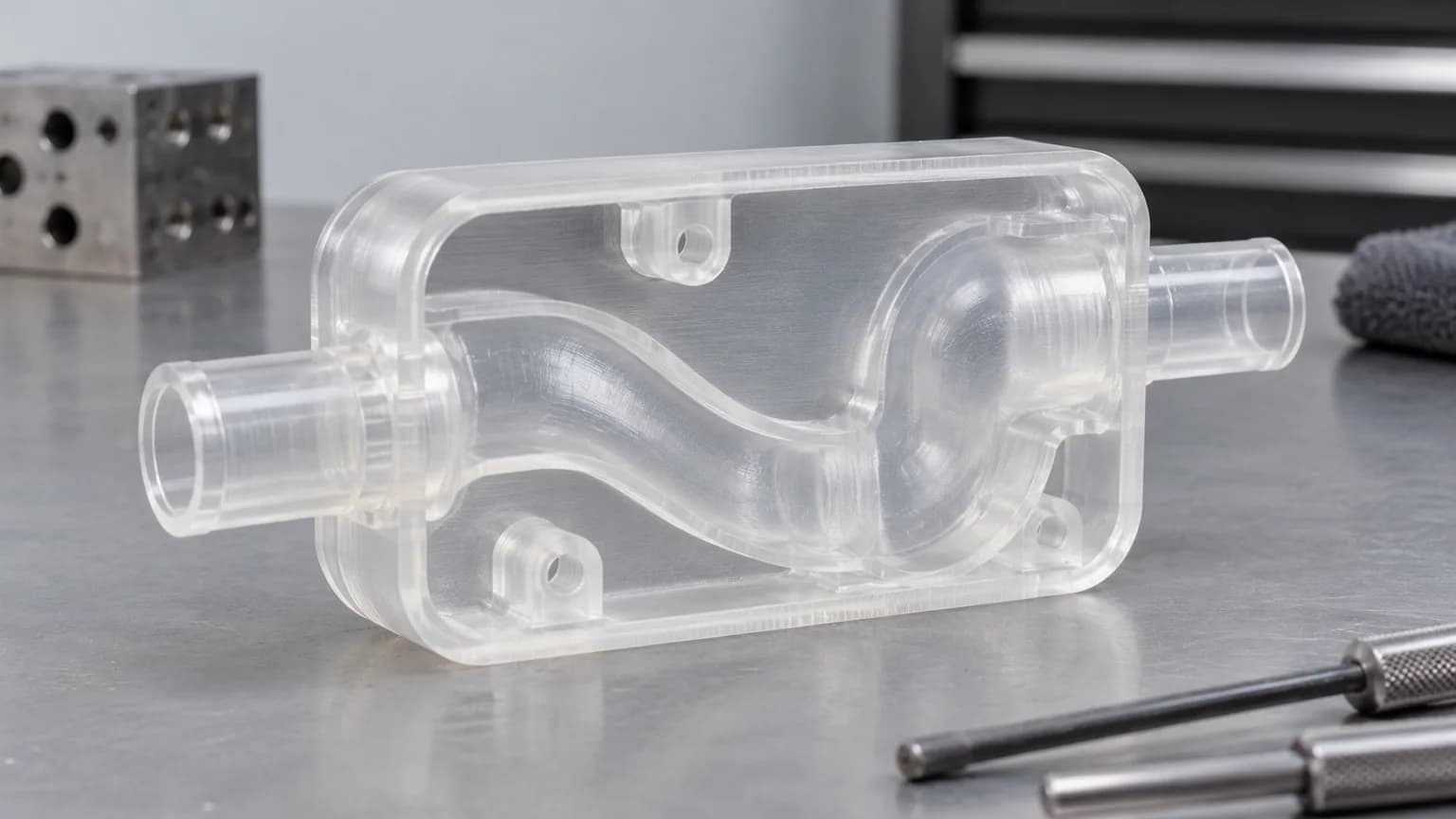
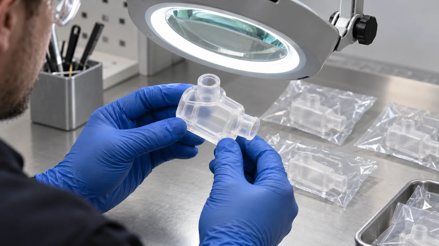
The clear-body drawing identified both dimensional checks and passage checks. Small openings needed visual inspection under magnification, and the drawing required a channel check with clean compressed air to establish that the route was open. External supports had to be removed, with a smooth handling surface free of sharp projections. These instructions translated the function of the part into practical shop-floor checks.
A passage can look correct at its entrance while holding residual material farther inside. Looking closely at the opening and checking continuity through the channel answer different questions. Planning both checks early helps establish where access is needed and whether a bend, branch or narrow opening will be difficult to finish.
Connection geometry deserves the same attention. A port diameter affects how tubing or a mating component fits, while the position and angle of the port affect access during assembly. Our SLA design guide recommends evaluating mating features on an initial part. A small interface sample can resolve a fit before the complete body or a larger batch is produced.
First article inspection gives that sample a useful dimensional record. It can be included when configuring parts in our portal, concentrating the checks on the dimensions that matter to your assembly. For a fluid component, those might be a mating diameter, a seating face or the spacing between connections. The customer then has a measured starting point for fit and functional evaluation.
FinishingBuild Cleaning Into the Manufacturing Route
Internal passages need room for liquid resin to drain and for cleaning fluid to reach the surfaces. Supports also need an accessible removal route. A small change to the direction of a port or the opening of a recess can make a part much easier to finish while preserving the intended connection or flow path.
We plan orientation around those requirements. ClearVue supports are removed before final UV post-curing to help protect the part surface. Orientation also affects trapped resin volumes and bubble formation, so the shape is reviewed through its build sequence as well as in its finished position.
The specified Class VI cleaning route uses successive fresh-isopropanol cleaning stages, thorough drying, controlled post-curing and final inspection. The ClearVue cleaning procedure makes drying and handling part of the process. For the customer, this connects the selected material to a defined method of preparing the finished surfaces.
On this job, the manufacturing notes required the resin and cleaning-solvent batches to be recorded, and both were captured in the order record. The drawing also required individual protective packaging. That combination supports traceability and helps preserve the finished surface as parts move from inspection to the customer's assembly area.
Nylon Valve HardwarePut the Moving Features Into the Printed Geometry
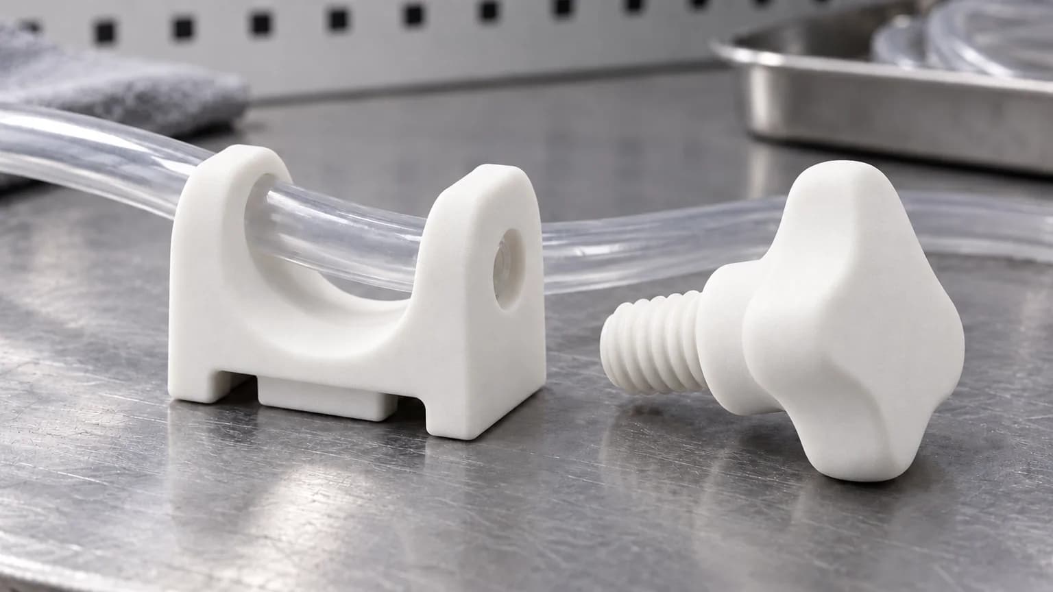
The separate nylon work addressed the mechanical side of fluid control. The parts were a pinch-valve body and its hand-operated knob. A pinch valve controls flow by squeezing flexible tubing, keeping the fluid within the tube while the surrounding mechanism applies the movement. This makes the body geometry, tubing clearance and feel of the control important design decisions.
The supplied models included coarse threads, openings through the body and shaped gripping surfaces on the knob. SLS formed those details directly in nylon, supported by the surrounding powder during printing. The threads and grip geometry could therefore be manufactured together with the main parts, without mould tooling or a separate machining operation to create each feature.
PA12 provides a useful balance of stiffness and toughness for this kind of hardware. The body needs to hold its shape around the mechanism, while the knob must tolerate handling and assembly. PA 2200 supports functional parts with printed threads, making it a practical choice for custom controls whose shape needs to follow the available space and the user's grip.
For a similar valve, generous thread roots help carry the turning load, and rounded contact features help guide the tubing into position. The clearance between mating printed parts affects how freely the control turns. Evaluating that fit with the intended tubing gives the designer useful feedback on assembly and operation before increasing quantity.
Here, the drawings specified PA 2200, a blasted finish and selected dimensional tolerances. Production instructions called for first article inspection against those drawings. Powder removal and surface finishing prepared the printed features for inspection, while the CAD model defined the remaining geometry. The customer received parts made to a consistent material and inspection requirement.
Make Useful Batches Without Waiting for a Mould
Both component families were manufactured in batches of dozens. At this scale, printing allows a design team to obtain a useful supply of custom parts while keeping changes accessible. Adjusting a connection, a clearance or a hand grip means updating the model and reviewing the affected features for the next build.
One nylon batch was completed and dispatched in six working days. The custom geometry moved from an order into finished components without a tooling stage. The clear bodies followed their own finishing and documentation requirements, with cleaning, drying and inspection included in planning the work.
Earlier respiratory-device work also included an urgent manifold project that moved from prototype to production in 72 hours, with a day of printing and a day of post-processing. That separate project shows the value of a direct route from CAD to manufactured parts when a design is ready and capacity is available. The part's geometry, selected material and finishing requirements set the schedule for each new order.
The Manufacturing ResultCarry the Design Intent Through to the Finished Part
Forge supplied the clear fluid bodies and nylon valve hardware as manufactured batches, with different process routes serving different jobs. SLA brought the passage and connection geometry into a transparent body. SLS brought the valve's mechanical and handling features into nylon parts. Drawings connected both routes to the checks and finishing the customer required.
The lesson for a new medical-device component is to develop the shape and its manufacturing route together. An accessible passage is easier to clean and inspect. A well-defined mating feature makes assembly easier to evaluate. A repeatable material, finishing and inspection specification gives the next batch a clear basis. Those choices turn additive manufacturing into a practical source of custom components for development and small-volume production.
Developing a Fluid Component or Custom Valve Part?
Share your CAD model, drawing and intended use. We can review the material, passage access, mating features and inspection needs, then plan a manufacturing route for your samples or production batch.
Discuss Your Medical Components