3D Printing Technology Database

Compare SLS, MJF, SLA, DMLS, FDM, and CNC production technologies. Access specifications, material compatibility, and design rules in an interactive guide.

Search the technology library
Categories

9 Technologies

TechnologyBuild VolumeLayer HeightToleranceLead TimeMaterials
CNC Machining
CNC Machining
subtractiveCNC
Aerospace BracketsMedical Instrumentation+2 more
1000×600×500mm (39×24×20")N/A (subtractive machining)±0.020mm12-16 business days7 available
Direct Metal Laser Sintering
metalDMLS
Aerospace ComponentsMedical Devices+2 more
380 × 284 × 380 mm (15 × 11.2 × 15 in)0.02 - 0.06 mm±0.2mm8-12 business days6 available
Fused Deposition Modeling
thermoplasticFDM
Aerospace ComponentsAutomotive Manufacturing+2 more
914 × 609 × 914 mm (36" × 24" × 36")127 - 330 microns±0.25mm2-4 business days7 available
Fused Filament Fabrication
thermoplasticFFF
Concept ValidationDesign Iteration+1 more
250 × 210 × 210 mm (9.8" × 8.3" × 8.3")50 - 300 microns±0.5mm1-3 business days4 available
Multi-Jet Fusion
Multi-Jet Fusion
thermoplasticMJF
Aerospace ComponentsAutomotive Manufacturing+2 more
380 × 284 × 380 mm (15 × 11.2 × 15 in)80 microns±0.3%4-8 business days2 available
PolyJet Matrix
PolyJet Matrix
resinPolyJet
Multi-Material PrototypesMedical & Anatomical Models+2 more
380 × 284 × 380 mm (15 × 11.2 × 15 in)0.028 mm (28 microns)±0.2%2-4 business days3 available
Stereolithography
Stereolithography
resinSLA
Visual PrototypesJewelry & Detailed Parts+3 more
1500 × 750 × 550 mm (59 × 29.5 × 21.7 in)0.025 - 0.150 mm±0.25%2-4 business days5 available
Selective Laser Melting
metalSLM
Aerospace ComponentsMedical Implants+1 more
250 × 250 × 325 mm (10 × 10 × 13 in)0.02 - 0.05 mm±0.1mm10-14 business days4 available
Selective Laser Sintering
thermoplasticSLS
Aerospace ComponentsMedical Devices+2 more
340 × 340 × 600 mm (13.4 × 13.4 × 23.6 in)60 - 120 microns±0.25%2-4 business days4 available
Process Selection

Manufacturing Technology Overview

Benchmark polymer, metal, and hybrid manufacturing platforms by envelope, resolution, tolerances, and supported materials. Access the interactive database above to align the right process with program requirements.

Qualified processes
9

Production-ready polymer, metal, resin, and CNC platforms under one roof.

Material playbooks
37+

Process-locked powders, resins, and billets with traceable documentation.

Documented use cases
35+

34+ industries spanning aerospace, medical, energy, and consumer products.

Key Metrics

What differentiates each process

Align your tolerance stack, surface finish goals, and production plan with the platforms that excel in those areas. These benchmarks pull directly from our qualified machines and are backed by inspection data.

Production envelope
1500 × 750 × 550 mm
Single-build capacity

Largest Build Volume

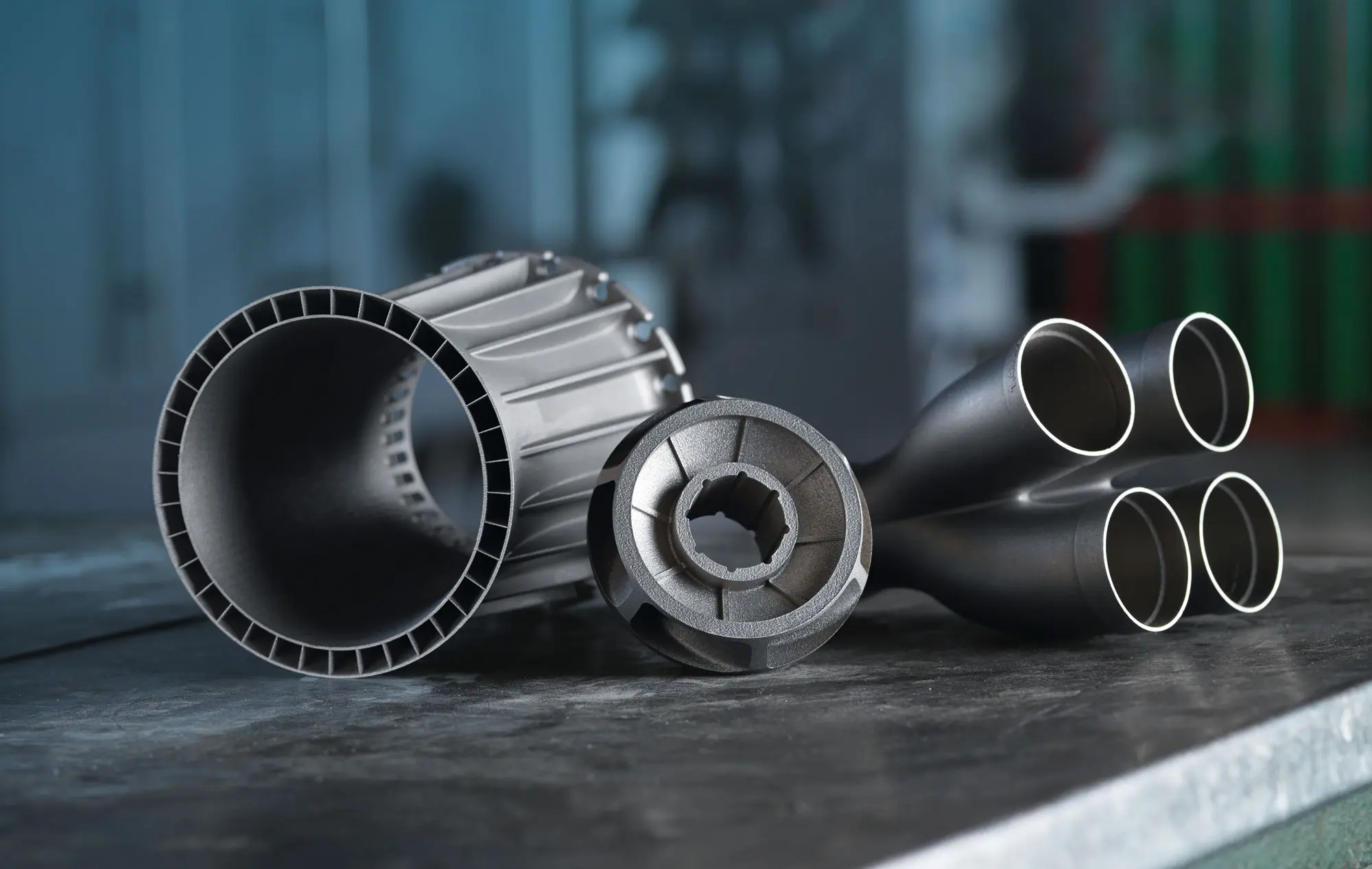
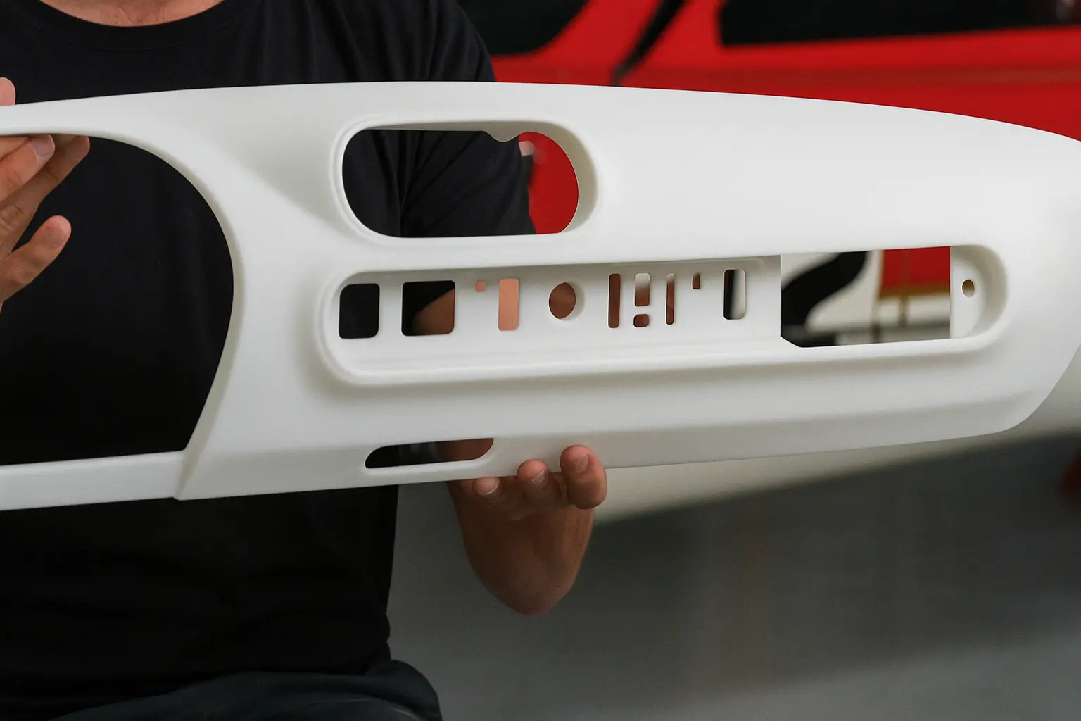
Large-format SLA enables full-scale prototypes, automotive panels, and industrial housings in a single build without segmentation.

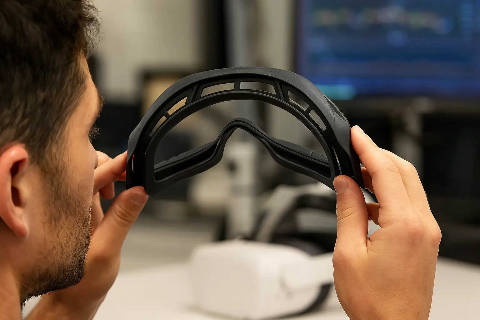
Ideal for visual prototypes, design validation, and customer presentations requiring full-scale accuracy.

Material versatility
10 materials
Engineering thermoplastics

Widest Material Coverage

From standard ABS to high-performance ULTEM and PC, FDM offers engineering-grade thermoplastics for diverse application requirements.

Pre-qualified materials with documented properties enable rapid material selection and qualification.

Batch production
No supports
Efficient part nesting

Highest Production Throughput

SLS enables dense part nesting without support structures, maximizing build chamber utilization for rapid turnaround on production volumes.

Powder bed technology allows efficient batch production with consistent quality across all parts.

End-use metals
±200 µm
Fully dense metal parts

Metal Additive Manufacturing

DMLS produces fully dense metal parts from titanium, stainless steel, aluminum, and Inconel for aerospace, medical, and industrial applications.

Complete thermal management and post-processing capabilities deliver production-ready metal components.

Technology Families

Manufacturing platform overview

Our manufacturing capabilities span polymer additive, metal additive, resin-based, and precision subtractive platforms. Each technology family delivers distinct advantages for specific material requirements, tolerance demands, and production volumes. From rapid prototyping to production-scale manufacturing, our industrial equipment and process expertise enable consistent quality across aerospace, medical device, automotive, and consumer product applications.

Powder Bed Fusion

Nylon & TPU Powder Bed Systems

Powder bed fusion technologies build parts layer by layer in a bed of thermoplastic powder, eliminating the need for support structures and enabling dense part nesting for efficient production. Both SLS and MJF deliver strong, functional nylon parts with isotropic mechanical properties, making them ideal for end-use applications. The self-supporting nature of powder bed processes allows complex geometries, snap fits, and living hinges that would be difficult or impossible with other additive methods.

Build functional prototypes and production parts without support structures, reducing post-processing time and material waste. Achieve efficient part nesting within the build chamber, maximizing throughput for bridge production and low-volume manufacturing runs. Access comprehensive finishing options including color dyeing, vapor smoothing, and cosmetic painting to meet aesthetic and functional requirements.

Nylon & TPU Powder Bed Systems manufacturing equipment
Additive4 materials

Selective Laser Sintering

Support-free manufacturing of complex geometries using engineering-grade nylon materials. High mechanical strength with uniform properties for functional prototypes and production parts with cost-effective batch manufacturing. This technology operates with build volumes up to 340 × 340 × 600 mm, achieving layer heights from 60 - 120 microns and maintaining tolerances of ±0.25% (Lower limit of ±0.25 mm).

Why teams choose SLS
  • No Support Structures
  • Cost-Effective for Complex Parts
Aerospace ComponentsMedical DevicesAutomotive PartsIndustrial Tooling
Additive2 materials

Multi-Jet Fusion

Precision engineering with fine detail resolution and excellent surface quality. Production-grade materials for strength and durability with scalable batch production. This technology operates with build volumes up to 380 × 284 × 380 mm, achieving layer heights from 80 microns and maintaining tolerances of ±0.3%, Lower limit of ±0.5 mm.

Why teams choose MJF
  • Excellent Detail & Precision
  • High-Speed Production
Aerospace ComponentsAutomotive ManufacturingMedical Device ManufacturingIndustrial Design

Understanding Powder Bed Fusion: SLS vs MJF

Both SLS (Selective Laser Sintering) and MJF (Multi Jet Fusion) are powder bed fusion technologies that build parts in a bed of nylon powder without support structures. While they share similar principles, MJF uses inkjet-applied agents and infrared energy, whereas SLS uses a laser to fuse powder. Each offers distinct advantages for different production scenarios.

SLS (Selective Laser Sintering)
  • • Laser-based powder fusion
  • • Proven technology with long track record
  • • Excellent mechanical properties
  • • Wide material variety (PA12, TPU, Glass-filled)
  • • Ideal for functional prototypes
MJF (Multi Jet Fusion)
  • • Agent-based infrared fusion
  • • Faster build speeds
  • • Superior surface detail and uniformity
  • • Consistent isotropic properties
  • • Optimized for production volumes

Note: Both technologies produce strong, functional nylon parts without supports. Choose SLS for proven material variety and established processes, or MJF for faster production, better surface finish, and higher throughput applications.

Material Extrusion

Industrial FDM & FFF Extrusion Printing

Material extrusion technologies build parts by depositing molten thermoplastic layer by layer. Industrial FDM (Stratasys) delivers engineering-grade performance, while FFF systems serve concept validation and prototyping needs.

Industrial FDM provides heated chamber control (90°C+), ±0.127mm accuracy, and engineering thermoplastics like PEEK, ULTEM, and Polycarbonate. FFF systems (Prusa, Ultimaker) offer accessible prototyping with PLA, ABS, and PETG at ±0.3-0.5mm accuracy for non-critical applications. Both technologies share material extrusion fundamentals but differ significantly in thermal management, precision mechanics, and material certification.

Industrial FDM & FFF Extrusion Printing manufacturing equipment
Additive10 materials

Fused Deposition Modeling

Industry-leading precision with best-in-class repeatability and layer adhesion using industrial-grade thermoplastics. This technology operates with build volumes up to 914 × 609 × 914 mm, achieving layer heights from 127 - 330 microns and maintaining tolerances of ±0.25 mm (Fortus 450) / ±0.762 mm (Fortus 900).

Why teams choose FDM
  • Large-Format Printing
  • Cost-Effective Manufacturing
Aerospace ComponentsAutomotive ManufacturingMedical DevicesIndustrial Design
Additive0 materials

Fused Filament Fabrication

Accessible extrusion-based 3D printing for rapid concept validation, design iteration, and non-critical prototyping with standard thermoplastic filaments. This technology operates with build volumes up to 250 × 210 × 210 mm, achieving layer heights from 50 - 300 microns and maintaining tolerances of ±0.3-0.5 mm typical.

Why teams choose FFF
  • Cost-Effective Prototyping
  • Fast Turnaround
Concept ValidationDesign IterationEducational Models

Understanding Extrusion Technology: FDM vs FFF

Within polymer extrusion, FDM (Fused Deposition Modeling) refers specifically to Stratasys's industrial-grade trademarked technology, while FFF (Fused Filament Fabrication) describes the broader category of consumer and prosumer extrusion printers. Though fundamentally similar in principle, these technologies differ significantly in precision, thermal control, and material capabilities.

Industrial FDM (Stratasys)
  • • Heated chamber environment (90°C+)
  • • ±0.127mm accuracy typical
  • • Engineering thermoplastics (PEEK, ULTEM, PC)
  • • Soluble support materials
  • • Production-grade reliability
Consumer/Professional FFF
  • • Heated bed only (ambient chamber)
  • • ±0.3-0.5mm accuracy typical
  • • Standard filaments (PLA, ABS, PETG)
  • • Basic PVA supports or same-material
  • • Concept validation and prototyping

Note: Forge Labs operates both industrial FDM systems and a Prusa FFF farm. While FFF is not a core production technology, it serves valuable roles in rapid concept validation and non-critical prototyping. For engineering applications requiring dimensional accuracy or material certification, industrial FDM remains the appropriate choice.

Vat Photopolymerization

Resin Platforms for High Detail

Photopolymer resin technologies cure liquid materials using UV light to create parts with exceptional surface quality and fine feature resolution. SLA uses laser-based vat photopolymerization for high-accuracy single-material parts, while PolyJet employs inkjet deposition for multi-material capabilities. Both processes excel at producing smooth surfaces, intricate details, and transparent components that require minimal post-processing. These technologies are ideal for applications demanding visual fidelity, dimensional accuracy, and complex geometries with undercuts or internal channels.

Achieve exceptional surface finish with sub-100 µm layer heights, ideal for visual prototypes, medical models, and precision assemblies requiring tight tolerances. Access specialized material formulations including rigid, flexible, transparent, and biocompatible resins validated against ISO 10993 and USP Class VI standards. Leverage advanced post-processing including UV curing, clear coating, and pressure dyeing to enhance mechanical properties and aesthetic presentation.

Resin Platforms for High Detail manufacturing equipment
Additive5 materials

Stereolithography

Ultra-high resolution resin parts with smooth surface finish and exceptional detail. This technology operates with build volumes up to 1500 × 750 × 550 mm, achieving layer heights from 0.025 - 0.150 mm and maintaining tolerances of ±0.25% (Standard) / ±0.4% (Large parts).

Why teams choose SLA
  • Highest Detail
  • Smooth Finish
Visual PrototypesJewelry & Detailed PartsMedical & Dental ModelsOptical Components
Additive3 materials

PolyJet Matrix

Multi-material 3D printing with exceptional detail resolution and the ability to combine rigid, flexible, and transparent materials in a single build. This technology operates with build volumes up to 380 × 284 × 380 mm, achieving layer heights from 0.028 mm and maintaining tolerances of ±0.2% (Lower limit of ±0.2 mm).

Why teams choose PolyJet
  • Multi-Material Integration
  • Variable Shore Hardness
Multi-Material PrototypesMedical & Anatomical ModelsConsumer Product DevelopmentAutomotive Interior Components

Understanding Resin Technologies: SLA vs PolyJet

Both SLA (Stereolithography) and PolyJet cure liquid photopolymer resins to create high-detail parts with smooth surfaces. SLA uses a laser to cure resin in a vat, while PolyJet jets droplets of photopolymer that are instantly UV-cured. Each technology excels in different detail, material, and application requirements.

SLA (Stereolithography)
  • • Laser-based vat photopolymerization
  • • Exceptional surface finish
  • • High accuracy (±0.05-0.1mm)
  • • Cost-effective for detail parts
  • • Wide range of engineering resins
PolyJet (Material Jetting)
  • • Inkjet-based photopolymer jetting
  • • Multi-material in single build
  • • Full-color capabilities
  • • Rigid, flexible, and transparent materials
  • • Complex assemblies without assembly

Note: Choose SLA for high-detail single-material parts with excellent surface finish and cost efficiency. Choose PolyJet when you need multi-material capabilities, overmolded assemblies, or parts requiring rigid and flexible materials in a single build.

Metal Additive

Metal Powder Bed Fusion

Metal powder bed fusion uses high-powered lasers to selectively fuse or melt metal powder layer by layer, creating fully dense metal parts with mechanical properties matching or exceeding traditionally manufactured components. DMLS (Direct Metal Laser Sintering) and SLM (Selective Laser Melting) both operate in controlled inert atmospheres to prevent oxidation, enabling the production of complex geometries impossible with conventional machining. These processes support aerospace-grade materials including titanium, stainless steel, aluminum, and Inconel for flight-critical hardware, medical implants, and high-performance industrial components. Integrated post-processing including stress relief, HIP, and CNC machining delivers production-ready parts with complete material traceability.

Manufacture fully dense metal parts from certified aerospace and medical-grade alloys with documented material properties and full traceability through AS9100-compliant workflows. Enable design optimization including topology-optimized structures, conformal cooling channels, and integrated assemblies that consolidate multiple components into single prints. Access complete post-processing capabilities including heat treatment, hot isostatic pressing (HIP), precision CNC machining, and dimensional inspection for end-use certification.

Metal Powder Bed Fusion manufacturing equipment
Additive6 materials

Direct Metal Laser Sintering

Fully dense, high-performance metal parts with exceptional strength for aerospace, automotive, and medical applications. This technology operates with build volumes up to 380 × 284 × 380 mm, achieving layer heights from 0.02 - 0.06 mm and maintaining tolerances of ±0.2mm to ±0.5mm (Size dependent).

Why teams choose DMLS
  • Fully Dense Metal Parts
  • Complex Geometries
Aerospace ComponentsMedical DevicesAutomotive ApplicationsIndustrial Manufacturing
Additive0 materials

Selective Laser Melting

Complete powder melting for ultra-high density metal parts with superior mechanical properties and fine surface detail. This technology operates with build volumes up to 250 × 250 × 325 mm, achieving layer heights from 0.02 - 0.05 mm and maintaining tolerances of ±0.1mm to ±0.3mm (Feature dependent).

Why teams choose SLM
  • Maximum Density
  • Superior Fatigue Performance
Aerospace ComponentsMedical ImplantsHigh-Performance Engineering

Understanding Metal 3D Printing: DMLS vs SLM

Both DMLS (Direct Metal Laser Sintering) and SLM (Selective Laser Melting) use lasers to fuse metal powder layer by layer. The key difference: DMLS sinters powder particles at a molecular level, while SLM completely melts the powder creating a homogeneous melt pool. This fundamental difference affects density, mechanical properties, and optimal applications.

DMLS (Direct Metal Laser Sintering)
  • • Sinters powder at molecular level
  • • 98-99% density typical
  • • Proven industrial track record
  • • Wide material compatibility
  • • Cost-effective for functional parts
  • • Excellent mechanical properties
SLM (Selective Laser Melting)
  • • Complete powder melting
  • • >99.9% near-theoretical density
  • • Superior fatigue performance
  • • Minimal porosity
  • • Ideal for aerospace & medical
  • • Enhanced mechanical properties

Note: Choose DMLS for proven industrial applications requiring strong, functional metal parts with excellent cost-to-performance ratio. Choose SLM when maximum density, fatigue resistance, and material properties are critical—particularly for aerospace, medical implants, and high-performance applications.

CNC & Hybrid

Precision Subtractive Manufacturing

5-axis CNC machining bridges additive finishes with tight tolerances, superior surface finish, and rapid turnaround.

Ideal for machined NPI parts, tooling, and secondary ops on additive builds. Handles aerospace alloys, engineering plastics, and composites with ease. In-process inspection and metrology maintain PPAP, FAIR, and AS9100 compliance.

Precision Subtractive Manufacturing manufacturing equipment
Subtractive7 materials

CNC Machining

Precision subtractive manufacturing for high-tolerance parts across metals and advanced engineering polymers. Multi-axis CNC milling, turning, and finishing deliver production-grade components with repeatable quality. This technology operates with build volumes up to 1000 x 600 x 500 mm, achieving layer heights from N/A and maintaining tolerances of +/- 0.020 mm achievable (material and geometry dependent).

Why teams choose CNC
  • Inspection-Ready Tolerances
  • Production Surface Quality
Aerospace BracketsMedical InstrumentationElectronics EnclosuresProduction Tooling
Resources

Documentation and playbooks

Every technology is backed by process design guides, finishing recipes, and compliance packets. Start with the most-requested downloads below or connect with engineering for program-specific documentation.

Selective Laser Sintering (SLS) Design Guidelines

Our Selective Laser Sintering (SLS) design guidelines help engineers and designers improve part quality, lower costs, and speed up production. Whether for prototypes or end-use parts, these best practices ensure strong, accurate SLS components with excellent surface finish and dimensional stability.

Stereolithography (SLA) Design Guidelines

Our design guidelines for Stereolithography (SLA) include important information to improve part quality, minimize costs, and reduce overall manufacturing time. By following the guidelines, you can produce high-quality parts, reduce expenses, and improve productivity.

Multi Jet Fusion (MJF) Design Guidelines

Our design guidelines for MJF include important information to improve part quality, minimize costs, and reduce overall manufacturing time. By following the guidelines, you can produce high-quality parts, reduce expenses, and improve productivity.

Inspection & compliance packets

AS9100 and ISO 9001 quality documentation, PPAP, FAIR, and C of C templates ready to pair with your build.

Ready to scope your next build?

Share tolerances, surface finish targets, and production volumes with our engineering team. We will recommend the best-fit technology, material, and inspection plan within one business day.