
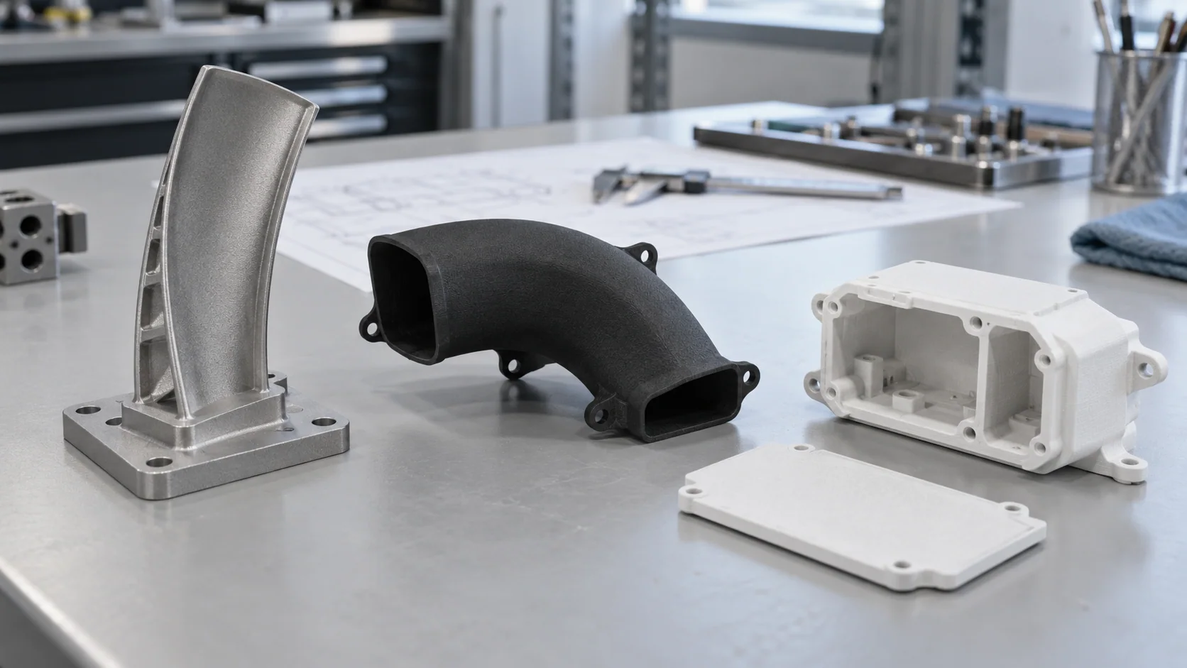
Aircraft development brings together parts with very different jobs. A curved metal section needs to hold its shape, a cooling shroud needs to direct air around nearby hardware, and a small UAV body needs space for electronics and access for assembly. Additive manufacturing lets each part take the form its job requires, with a material and finishing route chosen around that purpose.
These separate manufacturing examples show that approach in practice. Forge produced curved blade and hub sections in AlSi10Mg aluminum and a cooling duct in SLS Nylon PA12 for aircraft development work. A separate UAV project used SLS PA12 for a hollow main body, access hatches and battery-cover hardware. The common value was the ability to manufacture complex, application-specific shapes in small quantities and carry changes into the next version directly from CAD.
The Manufacturing Examples
- Curved metal sections: DMLS in AlSi10Mg aluminum
- Cooling shroud: SLS PA12 with integrated mounting tabs and a black finish
- Separate UAV assembly: natural-white SLS PA12 body, hatches and small retention parts
- Manufacturing scale: individual development parts and small batches of matching components
- Demonstrated turnaround: a nylon UAV component set completed in eight business days from ordering
Making Curved Sections in a Useful Engineering Material
The aluminum parts combined curved surfaces with thicker local sections. One represented a blade section; the other included a hub transition. Printing these local geometries makes it possible to examine a design in metal at a manageable scale. A small section can reveal how a curved surface meets its support, how an edge is finished or how the shape can be held during the next operation.
AlSi10Mg aluminum provides stiffness with relatively low weight, making it useful when a development part needs to hold its profile under handling or mounting loads. A metal section lets the team work with a rigid edge and a solid attachment region, then examine how those features can be finished and fitted into the surrounding assembly.
Direct Metal Laser Sintering builds the shape by selectively melting layers of powder. Curvature, varying section thickness and local attachment features can be formed together, with machining reserved for the surfaces that need it. For a small quantity, that gives the designer a direct route from a detailed model to a metal part without first creating casting tooling.
The surface and material condition belong in that decision too. A mating face may need machining, while a surface used to study airflow may benefit from a defined finish. Heat treatment can adjust AlSi10Mg's ductility and thermal conductivity. Choosing the required condition early helps the prototype answer the intended engineering question and gives the shop a clear finishing target.
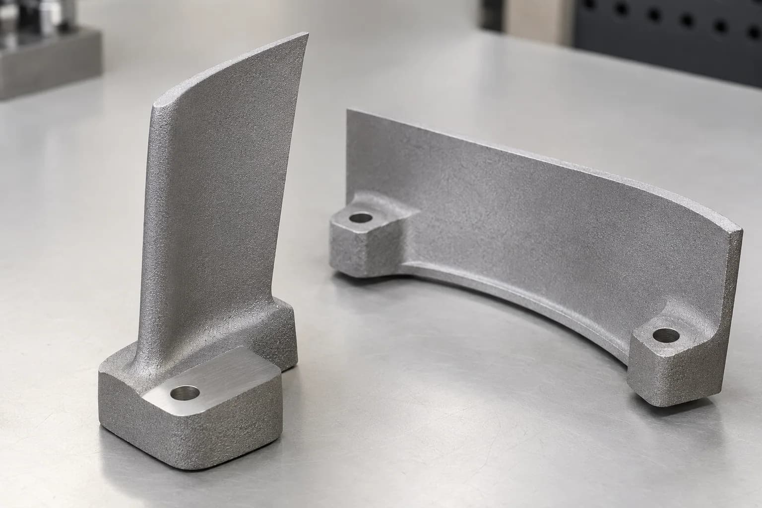
A local metal section makes curvature, transitions and finishing requirements tangible early in development.
Shaping Nylon Around the Air Path
The PA12 cooling duct had an open, curved form with mounting tabs built into its perimeter. Its geometry followed the available space around the hardware it served. That is a useful application for SLS: the air-guiding shape and the points that attach it to an assembly can be manufactured together, even when the surfaces change direction or sit at different angles.
A cooling shroud works by encouraging air to travel through the area that needs cooling. The fit around its edges matters because air also takes easier paths through gaps. A mounting tab that pulls a wall out of shape can change that fit. Smooth transitions, a clear outlet and mounting features placed around the intended seating surfaces help the designer make the airflow path and the mechanical attachment work together.
PA12 keeps a shroud light and provides the toughness needed to position it around surrounding components. Local ribs can firm up a wide wall, while rounded tab roots distribute fastening loads. Air temperature, nearby hot surfaces and the force at the fixing points guide material selection. Those conditions are useful to review together because a warm, continuously loaded mounting tab behaves differently from an unloaded wall.
The practical development benefit is being able to change the curve, outlet or attachment points together in CAD and manufacture the resulting shape. A prototype can then support a focused check of packaging, assembly access or airflow with the surrounding hardware in place.
UAV AssemblyA Hollow Body With Access Designed In
In the separate UAV project, the main body combined a rounded outer shell with a hollow interior, access openings and local mounting features. Hatches and smaller battery-cover components were supplied alongside it. This is where a physical prototype becomes especially useful: the team can handle the shell, reach the fasteners and see how components move through the available openings.
SLS supports the shape in powder during printing. Interior ribs and mounting pads can therefore be placed where the assembly needs them, and the outer surface can follow the desired profile. The large access openings also provide a route for removing loose powder from the interior after the build. Designing for assembly access and designing for cleaning often lead to the same useful openings.
The body and its small retention components have different stiffness needs. The shell benefits from consistent walls and local reinforcement; a narrow latch needs enough freedom to move during engagement. PA12 gives both a tough, lightweight starting material, while geometry controls their different behaviour. A broader radius at the root of a small feature spreads bending into the surrounding material and makes that transition easier to handle.
The manufactured files also included revised cover geometry. For a sliding or retained cover, adjusting the guide surfaces is a practical way to develop clearance without rebuilding the whole assembly. Keeping the mating features related in CAD helps a change remain coherent across the parts that touch.
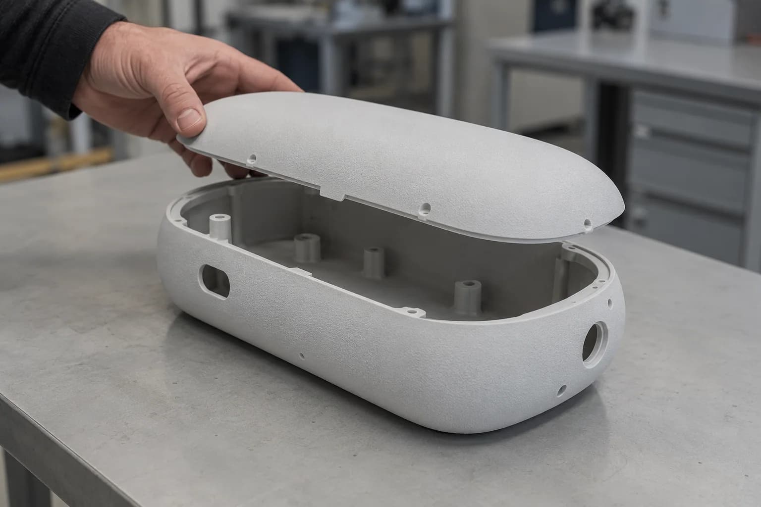
Access openings serve assembly, maintenance and powder removal while local ribs support the shell.
Giving Critical Surfaces the Attention They Need
A useful prototype starts with a clear purpose. For a metal section, the important feature might be the curved profile or a mating face. For a duct, it may be the clearance around a heat sink. For a hatch, the seating edge and latch engagement may determine whether assembly feels right. Identifying that purpose helps concentrate effort on the features that will teach the team something.
The CAD model defines the shape, and an engineering drawing can add the requirements that the model alone does not express. A short set of callouts can identify the reference surface for measurement, the fit at a hole, the finish on a working face or an area that needs machining. On a metal part, this also helps us place supports where they can be removed and finished without compromising an important interface.
For SLS assemblies, Forge's general PA12 tolerance is ±0.3%, with a ±0.3 mm minimum. That minimum matters on a small cover rail or latch clearance: dimensions that look comfortably separated on screen can meet much more closely after manufacturing. A short fit sample using the actual material can establish the clearance before the complete shell is ordered. First article inspection, available through our portal, can check agreed critical dimensions and provide a reference for further parts.
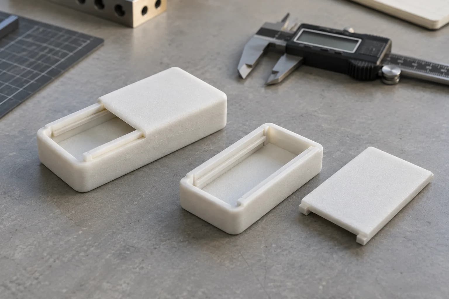
A physical fit check connects dimensions to the way a hatch seats, slides and closes.
Planning Printing, Finishing and Turnaround Together
The aluminum sections were supplied in their natural metal finish and reached manufacturing completion in about three weeks from ordering. Metal printing includes preparation for the build plate, support removal and the finishing required by the part. Our DMLS design guide explains how orientation, supported surfaces and machining access are considered together when planning that route.
For the nylon UAV components, the larger bodies ran on an EOS P 396, while the smaller hatch and retention parts used an EOS FORMIGA P 110. Printing started the next business day after ordering. Using machines suited to the different geometries let the small components progress alongside the larger shells, with the full set reaching manufacturing completion in eight business days.
SLS parts cool before they are unpacked, depowdered and bead blasted. Natural-white nylon gives the UAV components their finished colour; the separate black cooling shroud used a dyed finish. Openings and recesses are cleared during cleaning, and the surfaces selected for inspection can be checked in their finished condition. The quoted schedule accounts for that complete route as well as the printing itself.
These examples span individual metal sections and small batches of nylon assemblies. The same digital route supports both: released geometry goes into build preparation, and a revised design can be manufactured without changing a mould. For development work, that makes it easier to order a useful quantity of the current design and keep the next change focused on what the physical parts reveal.
The ResultMaking the Next Engineering Decision Easier
Forge delivered curved aluminum sections, an integrated nylon cooling shroud and a separate family of UAV body and access components. Each used additive manufacturing for a different reason: metal geometry in a small quantity, a shaped air path with its attachments, or a hollow assembly with accessible internal features. Together, they show how process choice follows the job of the part.
For your next aircraft or UAV prototype, start with what you need to learn from it. Material, orientation, finishing and inspection can then support that purpose. Explore our aerospace manufacturing capabilities or upload your CAD for a quote to develop a route from the current design to parts you can put to work.