

These flanged fittings needed mating threads printed directly from the model. Clear Accura ClearVue SLA resin made the first versions easy to inspect; a revised fitting moved to SLS PA12. Every round of fittings shipped within 4 business days, with no tapping or threaded inserts ordered.
These are development parts, ordered in ones, twos and threes, with no drawings, so every decision lived in the 3D files.
The Project at a Glance
- Application: flanged transition fittings and matching threaded collars for development test hardware
- Parts: two threaded transition designs in the 150 mm (6 in) class and a revision of the first; two matching collars under 90 mm across
- Processes: SLA in Accura ClearVue for two rounds, then SLS in Nylon PA12 for the revision, after a benchmark in SLA, FDM and MJF
- Finish: standard finish, ordered at 100 µm layers, with no polishing, dyeing, inserts or thread cutting
- Part definition: 3D CAD files only, with every thread modelled as real geometry
- Development: a three-process benchmark, clear SLA fittings and collars, then a revised fitting in SLS PA12
- Delivery: each round of fittings shipped 3 to 4 business days after the order, ahead of its target date
Rectangular-to-Round Transitions and Matched Collars
Each transition starts at a flat, rectangular bolting flange. A slot-shaped port in the flange face blends through a tapering body into a round neck, which ends in an externally threaded spigot set at an angle to the flange. Fittings like this typically join a slot-shaped port to round tubing or pipe. Both designs are in the 150 mm (6 in) class, with walls several millimetres thick. The second, added in the second round, has a larger port, a larger, coarser thread and a spigot set at a different angle to the flange.
Each transition has its own collar: a short, thick ring threaded on the inside to fit that spigot, with a counterbore and an inward lip at one end. Rings of this form are typically used as union nuts, drawing a mating part against the end of a spigot.
One interface held constant
Across all three transition designs, including the revision, the flange's overall size and bolt-hole positions never changed, and the revision kept the original thread size and pitch. Holding a bolted interface fixed while the rest of a part changes lets each new version mount on the same mating face, a pattern worth copying on any development fitting.
BenchmarkThree Processes on One Test Model, Before Any Fitting
The process comparison used the 3DBenchy, a widely used public test model, in clear Accura ClearVue by SLA at 100 µm layers, white ASA by FDM at 254 µm layers and HP PA12 by MJF at 80 µm layers. The model shows overhangs, small holes, fine detail and surface finish, so it gives a low-cost comparison before committing to a process.
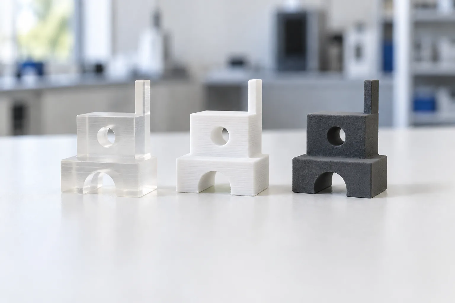
One small test model in three processes shows surface, detail and clarity side by side before a real part is ordered.
Both orders shipped on the same day, 7 business days after they were placed, one on its target date and one 4 business days early. The order that paired SLA with FDM shipped complete, so the clear prints, finished within 2 business days, waited for the FDM prints. If you want the quickest process back first, give it its own order or ask for a split shipment. The customer specified Accura ClearVue for every fitting in the first two rounds.
Process ChoiceWhy Clear Resin Suits the Early Rounds
3D Systems rates Accura ClearVue at 87.2% luminous transmittance and 4.3% haze (ASTM D1003) and describes it as having excellent humidity and moisture resistance. It lists fluid flow and visualization models among its applications. On a development fitting, seeing into the part helps whether or not anything flows through it. You can follow the passage from port to spigot, see how far a collar has run onto its thread and check that a seal or mating part sits square.
Clarity as printed
The 87.2% is a material figure. A printed part's clarity also depends on its surfaces: SLA parts carry fine layer lines and small support marks, and clarity improves with sanding and clear coating, which we offer on request. These parts shipped with the standard finish, without sanding or coating. If you need to see through a particular wall, say which when you order; our surface finishes page covers the options.
Where clear resin stops
Our ClearVue data lists 51 MPa tensile strength but only 6% elongation at break and a notched impact strength of 25 J/m, so the material is stiff and comparatively brittle. Its heat deflection temperature is 50 °C at 1.82 MPa, with a continuous-use range of 45 to 50 °C, and its resistance to strong solvents is poor. A clear fitting suits checking fit, form and assembly. Do not treat it as rated for process temperature, chemistry or pressure until it has been tested in those conditions.
Printed ThreadsThreads Printed Straight From the Model
In every file, the thread was modelled as true helical geometry: external threads on the three transition designs and internal threads in the two collars. That is what made them printable: a cosmetic thread annotation in CAD, or a callout on a drawing, exports as a plain cylinder or bore, and that is what prints. No tapping, chasing or inserts were ordered, and each collar was ordered in the same round and material as its transition.
The threads are straight (parallel), a finer pitch on the smaller pair and a coarser one on the larger, both far above the M6 minimum in our SLA design guide. When both halves of a thread are printed, size is not the only rule:
- Prefer coarse pitches and thread profiles designed for plastics. Our SLA guide recommends coarse pitches for durability, and deeper teeth keep more engagement once the tolerance is taken out of both halves.
- Put the clearance in the model. Our SLA and SLS guides both recommend a 0.5 mm clearance offset on printed threads to allow for thermal shrinkage. Each printed half also carries its own tolerance, so two halves drawn to the same nominal size can bind.
- Relieve the thread ends. A relief groove where a thread meets a shoulder lets the mating part run fully home instead of stopping on a partial thread form. The revised transition in this job added relief grooves at both ends of its thread.
- Expect friction and wear. Printed threads wear with repeated assembly, and the as-printed surface adds friction. For small, often-used threads, SLS nylon accepts heat-set inserts; in SLA resin, inserts are bonded instead.
Tolerance on a printed thread
Our standard tolerance is ±0.25% with a ±0.25 mm minimum for SLA, and ±0.3% with a ±0.3 mm minimum for SLS PA12. On threads tens of millimetres across, the minimum governs, so a printed thread diameter can sit up to 0.25 mm (SLA) or 0.3 mm (SLS) either side of the model, and both halves of a pair carry that band. Across a 150 mm-class transition the proportional term takes over: about ±0.4 mm in SLA.
Part DefinitionNo Drawing, So the Model Is the Specification
None of the orders came with a drawing, and the files carried no tolerances, notes or material callouts. That is normal for development parts and works when both sides know what applies: the model is the master, the process's standard tolerance covers every feature and nothing is machined, tapped or finished unless the order says so.
A drawing earns its place when one feature matters more than the rest, and for a printed fitting a short one is enough. Mark the critical features and their limits, such as a sealing face or a thread, say whether printed threads may be chased or tapped afterwards, state the finish and declare the 3D model as master. Our guide to drawing reconciliation for 3D printing covers how that differs from a machining drawing.
RevisionsA Re-Export, Then a Real Revision
The second round repeated the first transition from a re-exported file. Its bytes differed from the first order's file, but the model did not: the geometry matched point for point, with identical volume, bounding box and face count. A re-export is not a revision: a changed checksum only means the bytes changed, so compare geometry before re-qualifying a part. Our cab HVAC ducts and enclosures case study shows the opposite case, where real changes were invisible in a rendered preview.
What the revision changed
The revised transition changed in these ways:
| Feature | First design (clear SLA) | Revision (SLS PA12) |
|---|---|---|
| Flange size and bolt-hole positions | Set in the first round | Unchanged |
| Spigot | Projects well past the flange outline | At the second design's angle, almost entirely within the outline |
| Thread | Runs straight into the shoulder | Same size and pitch, relief grooves at both ends |
| Bore | Slightly tapered | Straight |
| Flange | Square corners | Slightly thinner, rounded corners, slightly larger bolt holes |
| Bounding box | Baseline | About a quarter shorter, about a fifth smaller by volume |
| Material volume | Baseline | About 13% less |
A smaller envelope also matters in a powder bed. SLS price follows the volume a part sinters and the space it takes in the build, so a spigot pulled almost inside the flange outline takes less of a build and nests more easily among other parts. Check what an angle or protrusion costs in envelope before you freeze it.
Material ChangeMoving the Revision to SLS PA12
Three pieces of the revision were ordered in SLS PA12, in the material's natural white. Moving from clear resin to SLS PA12 changes these properties:
| Property | Accura ClearVue (SLA) | SLS PA12 |
|---|---|---|
| Appearance | Clear: 87.2% luminous transmittance, 4.3% haze (3D Systems) | Opaque, natural white |
| Tensile strength | 51 MPa (our data) | 50 MPa in X, Y and Z (Evonik INFINAM PA 6002 P); 48 MPa X/Y, 42 MPa Z (EOS PA 2200) |
| Elongation at break | 6% (our data) | 16% X, 8% Y and Z (Evonik); 18% X/Y, 4% Z (EOS) |
| Heat deflection | 50 °C at 1.82 MPa (our data) | 64 °C X, 57 °C Z at 1.8 MPa (EOS PA 2200) |
| Threaded inserts | Bonded only | Heat-set inserts available |
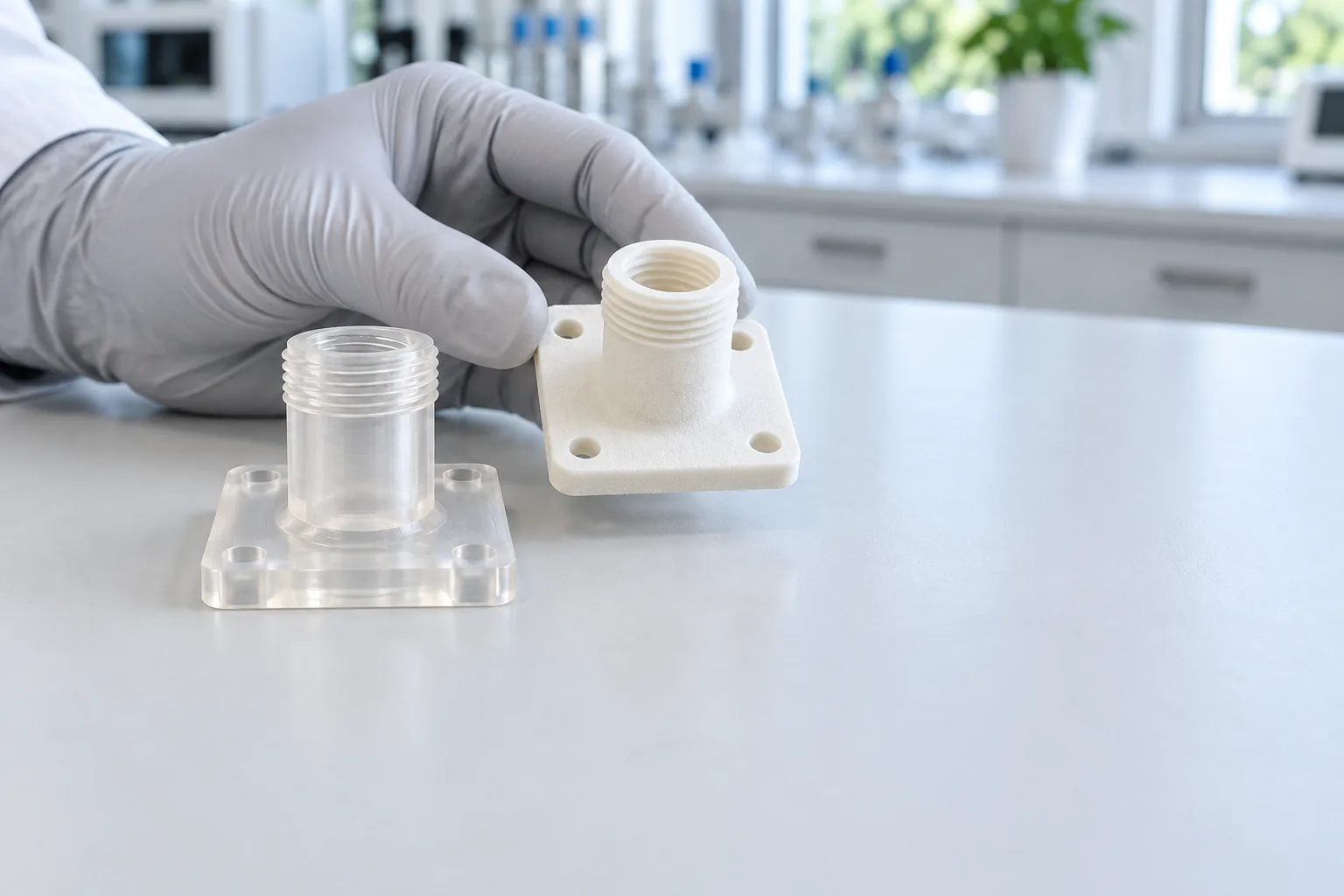
Moving a fitting from clear resin to SLS PA12 trades the view inside for a higher elongation at break.
Elongation at break rises from 6% to 16 to 18% in the strong direction, and EOS lists a higher heat deflection temperature for PA 2200 (64 °C X at 1.8 MPa) than the 50 °C our data gives for ClearVue. But EOS lists only 4% elongation in Z for PA 2200, so a thread pulled across the layers is loaded in its weakest direction; if a printed thread carries load, ask how the part will be oriented. Powder-bed parts also need no supports, so threads and bores have no support marks to remove.
Polymer or metal while the design is moving
Metal is the next step when temperature, chemistry or pressure call for it. EOS gives about 100% density for Ti64 and 316L. DMLS prints a fitting like this with its threads in place, and critical threads or sealing faces can be machined afterwards on our hybrid manufacturing route. In our online quoting, though, DMLS titanium and 316L default to a much longer lead time than SLS PA12 or ClearVue. While a fitting is still changing between rounds, polymer keeps each loop short.
ProductionHow Each Round Ran Through the Shop
Every order shipped complete in one shipment, on or before its target date. Our per-build records cover only the SLS round; for the earlier rounds the record runs from order to shipment.
| Round | Parts | Order to ship | Against target |
|---|---|---|---|
| Benchmark | Two test prints in each of SLA, FDM and MJF (two orders) | 7 business days | On the target date; 4 business days early |
| 1 | One transition and two collars, clear SLA | 3 business days, excluding a public holiday | 1 business day early |
| 2 | Two of the first transition, three of the second and three collars, clear SLA | 4 business days | 2 business days early |
| 3 | Three revised transitions, SLS PA12 | 4 business days | 4 business days early |
The SLS round
The revised parts joined a shared SLS build on an EOS P110 Velocis the next business day. The build ran for about 14 hours; combining small orders avoided waiting for one order to fill the bed. The build record holds the machine, process temperatures and X/Y shrink scaling, about 3% on each axis, to compensate for PA12 shrinking as it cools. Cooling, breakout, depowdering and packing took about 2 business days after the scheduled build finish, and the parts shipped inside the quoted delivery window.
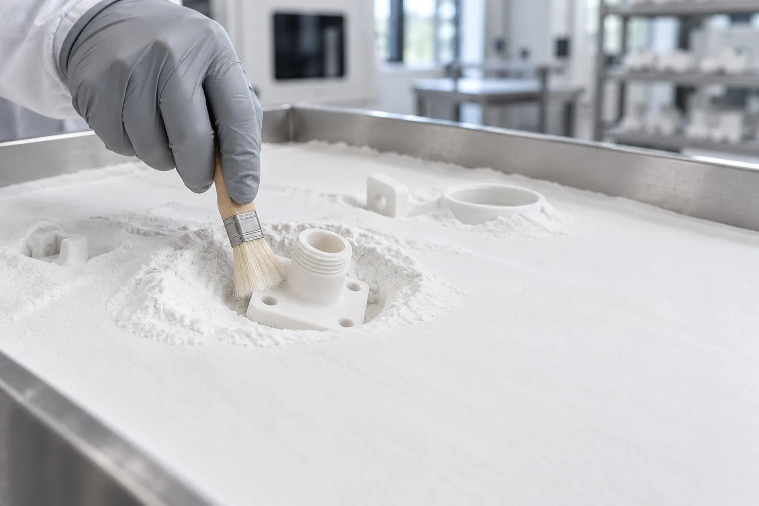
Small orders share an SLS build instead of waiting to fill a bed on their own.
Where the time went
Manufacturing took 3 to 4 business days per round of fittings. Schedule design, assembly and testing around that manufacturing window. Our repeat SLS PA12 production case study shows the same shared-build scheduling on production reorders.
OutcomeWhat the Five Orders Delivered
- Process changes without tooling: a three-process benchmark led to clear SLA fittings and a revised fitting in SLS PA12.
- Short loops: each round of fittings shipped 3 to 4 business days after the order, 1 to 4 business days ahead of its target date.
- Threads from the model: external and internal threads printed from modelled helical geometry, with no tapping, chasing or inserts ordered.
- Clean records: no nonconformances or complaints recorded.
What to Apply to Your Own Development Fittings
- Benchmark processes on a small test model first. Test prints in each candidate process show surface, detail and clarity side by side for little cost. If one process will finish first, order it separately or ask for a split shipment.
- Use clear resin for fit and form, within its limits. Our ClearVue data lists 6% elongation and a 50 °C heat deflection temperature at 1.82 MPa, so test before trusting it in process conditions.
- Model threads as real geometry. A cosmetic thread prints as a plain cylinder. Model the helix on both halves, and print each pair in the same material and round.
- Design printed threads for the process. Stay at M6 or larger, prefer coarse pitches and thread profiles designed for plastics, put a 0.5 mm clearance offset in the model and relieve the thread ends.
- Hold the interface fixed while the part changes. A constant flange size and bolt pattern lets each new version mount on the same mating face.
- Compare geometry to tell a revision from a re-export. A matching checksum proves a file is unchanged; a different one only means the bytes changed. Matching volume, bounding box and face count is a quick first check, and a point-by-point geometric comparison confirms it.
- Keep a moving design in polymer, and price alternatives on one file. Quoting one file in resin, nylon and metal shows the cost and lead-time trade-off.
- Plan around design time, not print time. When each round ships in 3 to 4 business days, design and testing set the schedule.
Could Your Fittings Be Printed This Way?
Good candidates are development fittings made in ones, twos and threes while the design is still moving: port adapters, rectangular-to-round transitions, manifold blocks, union collars and fixtures with integral threads. Clear SLA suits early rounds where seeing inside is useful and conditions are mild. SLS PA12 suits rounds that need more ductility, and DMLS suits a settled design or a condition polymer cannot meet.
Compare your fluid, temperature and cleaning chemicals with the supplier data for each material, and test printed fittings in the real conditions before relying on them. The material pages for Accura ClearVue and Nylon PA12 are the place to start.
For design rules, see our SLS design guide; for development rounds like these, see our rapid prototyping service. For more energy applications, see 3D printing for energy and clean tech and our case studies on touch-proof high-voltage covers in MJF PA12 and DMLS pistons and engine parts from machining drawings; for another job made from 3D files alone, see hairpin stator assembly nests in SLS PA12.
Developing Fittings, Manifolds or Test Hardware?
Send us the files, the quantity per round and the conditions the part will see. We will recommend a process and material for each stage of the design, from clear resin to nylon or metal. Lead times start at 2 business days, 24-hour turnaround is available on request, and we offer next day shipping anywhere in the US and Canada.
Discuss Your Fittings With Us