

These MJF PA12 electrical covers came with drawings that specified much more than dimensions: build direction, GD&T, marking, packaging and documentation. Turning those notes into a production plan meant defining the inspection and finishing steps before the parts entered production.
On a drawing-controlled printed part, most decisions are made before anything is printed. One support was ordered and delivered on its own first, and the production order, a few dozen of each part, was placed well ahead of the date the parts are needed. The production lot has not shipped yet, so this post covers the drawing review and order set-up rather than build results.
The Project at a Glance
- Application: a touch-proof cover for high-voltage connections, a low-voltage connection cover and a small support ring on fuel cell equipment
- Parts: a box-like shroud in the 150 mm (6 in) class; a long, shallow cover in the 350 mm-plus class; a support ring under 40 mm across
- Process and material: MJF PA12, solid, as each drawing specifies, ordered in HP PA12
- Part definition: customer drawings with GD&T to ASME Y14.5, ISO 2768 tolerance classes, a specified build direction, part marking and labelled packaging to the customer's specification and a REACH declaration with the first article
- Orders: one support delivered first, then a production order for a few dozen of each part, on the geometry first quoted
- Quality: a first article inspection and a bounding-box check on every part, written into the order at review
Two Covers and a Support Ring
Fuel cell equipment carries DC connections at voltages where every exposed connection needs a guard. A touch-proof cover is that guard, keeping fingers and tools off live conductors during assembly and service. Its protection comes from its shape and fixing, not the plastic alone, so the drawing controls the shape closely. Proving touch protection is part of the customer's own product testing.
The high-voltage cover is a box-like shroud on a short mounting flange. The low-voltage cover is long and shallow, with openings, internal ribs, bosses and mounting lugs with holes and slots. Both have even walls, a few millimetres thick; our MJF design guide recommends even walls to limit distortion. The third part is a small nylon support ring under 40 mm across.
Process ChoiceWhy MJF PA12 Suits Low-Volume Covers
The process was not ours to choose: every drawing names Multi Jet Fusion and calls for solid parts. It is a sound choice, and the reasons carry over to similar parts. Moulded, each part would need its own tool, complicated by openings, ribs, bosses and lugs, and paid off over a few dozen parts per order. In a powder bed those features need no supports, draft or side actions, and a revision is a new file.
Strength across the layers
MJF PA12 combines the stiffness to hold a cover's shape with the toughness to handle fitting and removal. That balance matters around the mounting lugs: these small features carry the fastening loads while the wider walls enclose the connections. Rounded transitions from each lug into the wall spread that load, and ribs can stiffen a long cover while keeping its walls light and even.
MJF PA12 also retains much of its ability to stretch before breaking across the printed layers. That is useful when lugs and walls face different directions and flex slightly during assembly. SLS PA12 also makes durable covers, with more attention to build direction where slender features need to flex across the layers. For either process, the material choice works alongside the geometry: flange flatness and mounting-hole position determine how neatly the cover seats, so those are useful features to check at first article inspection. Our MJF vs SLS comparison covers the wider trade-offs.
What "solid" rules out
MJF fuses each cross-section fully, so an MJF nylon part has no infill setting. The note still matters: with the process named and the part called solid, a supplier cannot hollow the walls, add a lattice or switch to a process where infill is a variable without a written deviation, which protects a part whose job is to be a continuous barrier.
The DrawingReading the General Notes as a Process Specification
General notes on drawings like these each map to a step in production. Read them that way before quoting: a note missed at quote becomes a rejection at first article.
| Drawing requirement | What it becomes in production | When it is settled |
|---|---|---|
| Process named, solid | The named process, solid, on every line; any change needs a written deviation | Quote |
| Specified build direction | First article and every later lot built the same way up | Build preparation |
| GD&T to ASME Y14.5 | Basic dimensions and profile tolerances to datums; parts judged against the 3D model | First article |
| ISO 2768 tolerance class | A fallback for any plain dimension | First article |
| Part marking and labelled packaging to the customer's specification | Marking method approved in writing; label content taken from the drawing at order review | Before production |
| Clean, burr-free supply | Powder cleared from every hole and recess, checked part by part | Every part |
| REACH declaration with the first article | Material declarations gathered from the powder supplier and any finishing step | Before the first article ships |
Our standard MJF finish is bead blasted, a uniform, slightly grainy matte texture. Powder-bed parts have no supports, so there are no witness marks to dress; the cleanliness risk is unfused powder held in small blind holes, counterbores and recesses, which has to be blasted out and checked on every part, not on a sample.
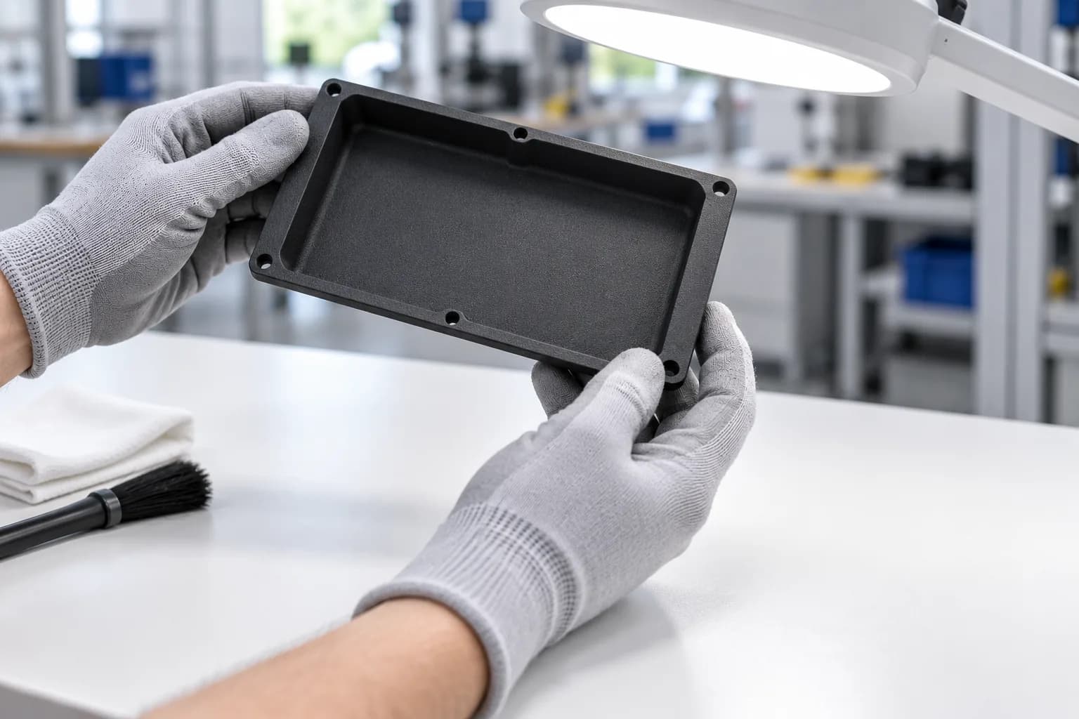
A clean, burr-free note on the drawing makes powder removal from every hole and recess a checked step.
What a Specified Build Direction Buys, and What It Costs
The drawings specify the build direction. For flanged covers the usual choice is flange first, top face last; for a ring, an end face down with the bore vertical. That buys two things:
- Every lot is built the same way. Printed nylon is not identical in every direction, as HP's elongation figures show. A fixed orientation makes the first article represent every later lot, with the layers running the same way through every feature.
- Holes run along the build axis. With the flange built first, bolt and locating holes through it run vertically. Our MJF design guide notes that vertical holes print more accurately than horizontal ones, which can resolve as ovals, so this orientation suits datum holes best.
The cost is nesting freedom. The HP Jet Fusion 5200 and 4200 have a 380 × 284 × 380 mm build volume. Laid flange-down, the long cover takes up most of the platform's length, which leaves little room to angle it across the bed. Check the longest dimension in the specified orientation against your supplier's usable bed, after scaling and edge clearance, before the drawing is released; our guide to part orientation covers the trade-offs.
Flat flanges are the feature to watch
A cover that seats on a flange usually carries a flatness callout there, often as the primary datum. Our MJF design guide warns that parts with large flat planes are likely to warp, and a long, thin flange printed as the first layer is exactly that geometry. If a flange is always bolted down in service, a drawing can call for flatness to be checked in that restrained condition, which tests the part the way it is used.
TolerancesProfile to Datums, and Where ISO 2768 Fits
A model-based scheme suits printed parts: the 3D model is the complete definition, dimensions are basic and one general profile tolerance to datums controls every surface without its own callout. On a drawing like that, the ISO 2768 class in the title block is a fallback that governs very little.
A profile tolerance is the total width of a zone around the true surface, so a 0.6 mm profile allows ±0.3 mm; halve it before comparing it with a process tolerance. Ours for MJF PA12 is ±0.3% with a ±0.5 mm minimum, and the minimum governs up to about 167 mm. Compare each part's profile zone with the process tolerance on its own: a large part can carry a looser zone than a small, precise one, because function sets the number, not size.
When a zone or hole is tighter than the published standard, settle it at review rather than at first article: either the designer opens it where function allows, or the supplier confirms it on measured first articles. For holes, our MJF design guide suggests printing them undersize and drilling them out where higher accuracy is required.
On drawings like these, a few hole, slot and flatness callouts are tighter than the general profile. Locating holes are often given position tolerances at maximum material condition (MMC), so a hole made larger than its smallest allowed size gains bonus position tolerance, and datum features referenced at MMC let the pattern shift as a group. At review, we wrote a first article inspection and a bounding-box check on every part into the order. The per-part check catches gross shrink or warp; the tighter hole, slot and flatness callouts are what a first article should measure first.
Where ISO 2768 sits against MJF
ISO 2768-1 sets general tolerances for linear dimensions in four classes, fine (f), medium (m), coarse (c) and very coarse (v), written with machining in mind.
| Nominal size | ISO 2768-1 m | ISO 2768-1 c | ISO 2768-1 v | Our MJF standard |
|---|---|---|---|---|
| 0.5 to 3 mm | ±0.1 mm | ±0.2 mm | No value | ±0.5 mm |
| Over 3 to 6 mm | ±0.1 mm | ±0.3 mm | ±0.5 mm | ±0.5 mm |
| Over 6 to 30 mm | ±0.2 mm | ±0.5 mm | ±1 mm | ±0.5 mm |
| Over 30 to 120 mm | ±0.3 mm | ±0.8 mm | ±1.5 mm | ±0.5 mm |
| Over 120 to 400 mm | ±0.5 mm | ±1.2 mm | ±2.5 mm | ±0.5 mm up to about 167 mm, ±1.2 mm at 400 mm |
Our standard meets coarse from 6 mm up and very coarse wherever that class gives a value, but it is looser than medium at almost every size, matching it only between about 120 and 167 mm. A printed part drawn to ISO 2768-m therefore needs a profile tolerance or local callouts that override the class, or agreed tolerances on the dimensions that matter. See our article on drawing reconciliation for 3D printing.
Part MarkingPrint the Part Number In, Plan the Serial Number
The support ring's part number is modelled into its CAD as raised characters on a vertical wall, a couple of millimetres tall and about 1 mm proud. Our MJF design guide suggests at least 10 point bold text on vertical walls and 16 point bold on top and bottom planes, with embossed detail at least 1 mm wide and 0.5 mm high. A fixed mark like this costs nothing extra to print and cannot fall off.
When a drawing calls for a per-part identification number as well as a part number, that number cannot come from a single file: the options are a unique file per part, a mark added after printing or a label, each with its own effect on build preparation, traceability and cost. Settle the method in writing before the first lot.
ColourWhen an MJF Drawing Says Black
When an MJF drawing calls for black PA12, that is a finishing decision. MJF PA12 comes out of the machine charcoal grey and can stay that way with no extra step. Black is added by dyeing, which we do in-house on DyeMansion equipment. DyeMansion gives the penetration as up to about 0.2 mm, depending on the material, so the colour sits in a surface layer and a deep scratch can show grey underneath.
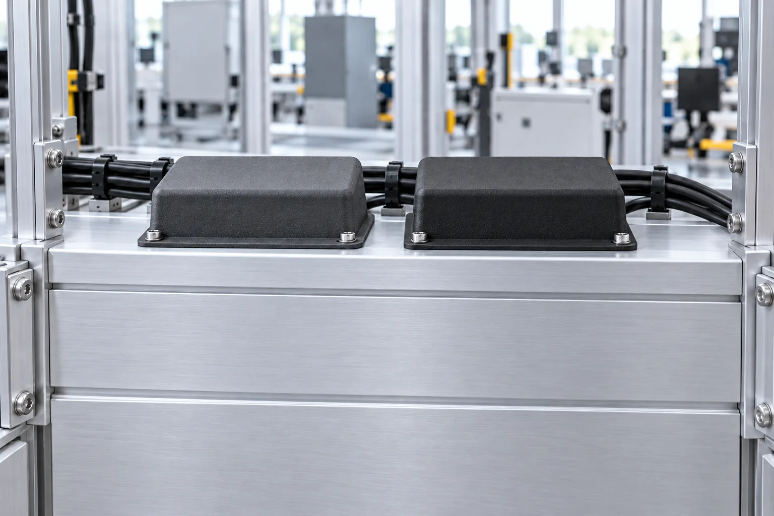
MJF PA12 comes out charcoal grey; black is a separate dyeing step, so the drawing should say which.
On a drawing-controlled part that has consequences. Dyed parts spend time in a heated water bath, so measure first articles after dyeing if a dimension is critical. The dye becomes part of the article, so a REACH declaration has to cover it as well as the powder. And "black" can mean dyed, painted or coated, which wear differently. Write "dyed black" or "natural grey (charcoal)" on the drawing and PO before quoting.
DocumentationPaperwork Is Part of the Delivery
The drawings ask for a REACH declaration with the first article and labelled packaging; the purchase order adds a certificate of conformance with every lot. Each has its own lead time, and the first article cannot ship without them.
Under the EU REACH regulation, a supplier of an article must pass on information when a substance of very high concern on the Candidate List is present above 0.1% by weight. For a single-material printed part the declaration rests mostly on the powder supplier's declarations, plus anything finishing adds, so ask for them when the order is placed. A certificate of conformance should identify the part, drawing revision and lot, and name the process and material actually used; it should be signed and dated.

A drawing's packaging note sets the label content, so settle it before production, not at the packing bench.
What the Order Includes
On a first lot like this, the first article, marking approval and paperwork set the calendar, not print time, so order ahead and let them close before the lot is due. The order as placed carries:
- The quoted geometry: the part geometry ordered is the geometry first quoted.
- The drawing's process: every line quoted and ordered in MJF HP PA12, solid.
- Inspection written in: a first article inspection and a bounding-box check on every part.
- Documents on the order: the drawings and PO call for labelled packaging, a certificate of conformance with every lot and a REACH declaration with the first article.
What to Apply to Your Own Drawing-Controlled Parts
- Read the general notes as the process specification. Map each note to a step in the order before quoting.
- Name the process and say solid only when you mean it. It rules out hollowing, lattices and substitution, which protects a barrier part but also removes options.
- Specify a build direction where it buys something. It makes the first article represent every lot and can put datum holes along the build axis, but it fixes nesting, so check the part in that orientation against the bed.
- Compare the profile zone, not the title-block class, with the process. Halve the profile value and set it against the process tolerance: ±0.3% with a ±0.5 mm minimum for our MJF PA12.
- Know where ISO 2768 sits against printing. Our MJF standard meets coarse from 6 mm up, but is looser than medium at almost every size.
- Treat long flat flanges as the risk feature. Call flatness only where the part seats, consider a restrained-condition check for bolted flanges and plan inspection around it.
- Model fixed part numbers into the CAD, and plan serial numbers. Per-part numbers need an agreed method, approved in writing before the first lot.
- Write "dyed black" or "natural grey", not just a colour. Dyeing affects when first articles are measured and what the REACH declaration covers.
- Order ahead and put the paperwork on the PO. On a first production lot, approvals and declarations set the calendar, not print time.
Could Your Covers and Guards Be Printed?
Good candidates are covers, shrouds, guards, connector housings and small supports for energy equipment, ordered in tens to low hundreds, where a mould would tie up money in a design that may still change.
Match the cover material to its working environment. For enclosures with specified flammability requirements, ULTEM 9085 offers a UL 94 V-0 rating at 1.5 and 3 mm, giving you a flame-retardant material option to include in the enclosure design; our UL 94 guide explains how ratings relate to wall thickness. MJF PA12 resists oils and greases, making it useful for covers near lubricated equipment. Hot coolant exposure deserves attention around loaded mounting lugs: immersion testing in 50/50 glycol coolant at 60 °C for six weeks caused slight softening, making stiffness under the expected exposure a useful design check for those features. For outdoor covers, UV-resistant ASA helps preserve appearance and toughness in sunlight; a UV-protective coating is another option for PA12.
See 3D printing for energy and clean tech, our end-use part manufacturing service and our case studies on DMLS pistons and engine parts from machining drawings, threaded flange fittings in clear SLA and SLS PA12 and repeat SLS PA12 production without tooling.
Have a Drawing-Controlled Part to Put Into Production?
Send us the files, drawings and quantities per lot. We will review every note on the drawing, from build direction to marking and declarations, before we quote. Lead times start at 2 business days, 24-hour turnaround is available on request, and we offer next day shipping anywhere in the US and Canada.
Discuss Your Parts With Us