
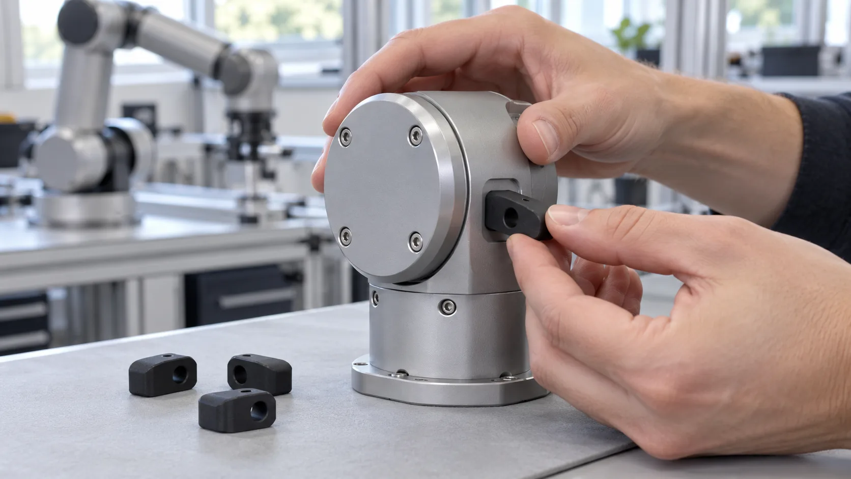
Small actuator parts are a useful production application for SLS: a lot can contain hundreds of detailed components without requiring a mould. For wearable robotics hardware, Forge Labs supplied repeat PA12 and TPU parts, using released files, recorded build orientations and separate handling of left- and right-hand versions.
This case study covers why SLS suits small actuator parts, how lots of hundreds share builds, what kept files, orientation and handed pairs consistent, how to read a drawing written for another process, and how a development stream ran beside production without disturbing it.
The Project at a Glance
- Application: the small parts of a powered joint actuator for a wearable robot, made in repeat lots with no moulds, alongside development parts and printed moulds and jigs
- Production parts: small travel stops, clamp plates, flexible cable clips and drive components
- Processes: SLS for the nylon and TPU parts, with logged nylon builds on EOS P110 machines; SLA, FDM and SLS for moulds and jigs
- Material and finish: Nylon PA12 in black, flexible SLS TPU and rigid resin selected by component function
- Orders: repeat lots of dozens to a few hundred, without production moulds
- Delivery: a median of five business days from order to ready
Four Part Families, Reordered Without Design Changes
The production parts are small enough to pack densely in a build. Their functions call for different geometries and materials.
- Travel stops. Left- and right-hand versions limit travel within the assembly. Similar-looking variants have different mating features and cannot be substituted for one another.
- Clamp plates. Thin plates combine recessed fasteners and locating features in a single print.
- Wire clips. Flexible TPU forms a screw seat and a retaining channel in one piece.
- Toothed drive pulleys. Rigid resin carries small drive features; the torque-transmitting bore needs particular attention during inspection.
| Part family | Material and finish | How it is ordered | What keeps lots consistent |
|---|---|---|---|
| Handed travel stops | SLS PA12, dyed black | Matched left- and right-hand quantities | A separate file per hand; bags marked by part number |
| Clamp plates | SLS PA12, dyed black | Small repeat lots | One file, and a note to repeat the previous orientation |
| Wire clips | SLS TPU, black | Quantities set to the assembly requirement | Model-based definition; re-exported files checked by volume and bounding box |
| Toothed pulleys | Rigid resin, black | Repeat production quantities | One unchanged file; the drive bore named for inspection |
Why Small Actuator Parts Suit SLS
No mould, and builds that are shared
The production parts are reordered in lots of dozens to a few hundred while development continues. A mould per design would tie up money and lead time; here every order went to production straight from a file. SLS price follows the volume sintered and the space a part takes in the build, and fingertip-sized parts take very little of either. A lot of hundreds fits in a single build on a compact machine, and a smaller lot rides alongside other jobs.
Features print in place
Counterbores, through bores, slots, pins and a hooked wire channel all form in the same pass. Unsintered powder supports every overhang, so there are no supports to remove and no draft to add. Our SLS design guide sets a 0.8 mm minimum pin diameter.
What PA12 brings to a travel stop
SLS PA12 combines low weight with toughness, making it a useful choice for compact stops and clamp plates inside a wearable actuator. Its ability to flex under load helps small features tolerate assembly and contact forces. A travel stop also benefits from a broad contact face to spread the load and rounded transitions to reduce stress where the stop joins the rest of the part. Build orientation places the loaded features in the direction best suited to those forces.
Fit matters just as much as material strength. Our standard SLS PA12 tolerance is ±0.3% with a ±0.3 mm minimum. On parts this small, that minimum band determines the clearance needed around locating features. Checking the first parts in the actuator helps establish a fit that assembles easily and positions the stop correctly.
ProductionHow the Lots Ran Through the Shop
The reviewed nylon build records show hundreds of small parts packed into compact SLS builds, with both hands represented where the order required matched pairs. Shared builds allow a small lot to run without occupying an entire machine. The production plan also needs to account for cooling in the powder before breakout.
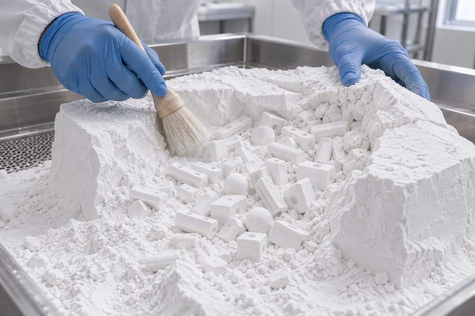
Fingertip-sized parts take little build space, so a lot of hundreds fits in a single compact SLS build.
The flexible clips ran in separate powder-bed TPU builds. Different materials require different build routes even when the components will be assembled into the same kit.
Printing is only part of the lead time
A fast print does not make the whole manufacturing sequence equally short. Cooling, breakout, inspection and finishing can occupy as much time as printing, so ask how the full route is scheduled.
Black by dyeing, and when colour can wait
SLS PA12 prints in natural white, and our in-house DyeMansion process adds the black finish after depowdering and bead blasting. Dye colours the nylon below the surface, giving small bores and mating features a black finish without a paint layer building up around them. A first-article fit check on the finished parts includes the complete manufacturing route. Natural white is also available for early prototypes when the priority is checking assembly fit.
Repeat ControlFreezing the File, the Orientation and the Pairs
One file per part, byte for byte
The reviewed repeat orders reused released files, with matching checksums available for several components. Re-exported files need a separate geometry check: matching volume and bounding box are useful screening measurements but do not prove that every feature is unchanged. Keep a controlled master file for each part and identify a new revision explicitly when the design changes.
The same orientation every lot
One clamp reorder carried a note to use the same build orientation as the previous order. Orientation affects how curved faces feel, where layer steps appear and how loaded features resist bending. Keeping it consistent helps a replacement clamp fit and behave like the part it replaces. Features that carry load or need a particular surface finish can guide the orientation agreed for production.
Handed parts are two parts
The stop orders paired the quantities of each hand and specified bags marked by part number. Two near-mirror parts this small are hard to tell apart by eye, so the bag label, not the part, carries the identification. Give each hand its own part number and file, order and build them as matched pairs, and bag them separately.
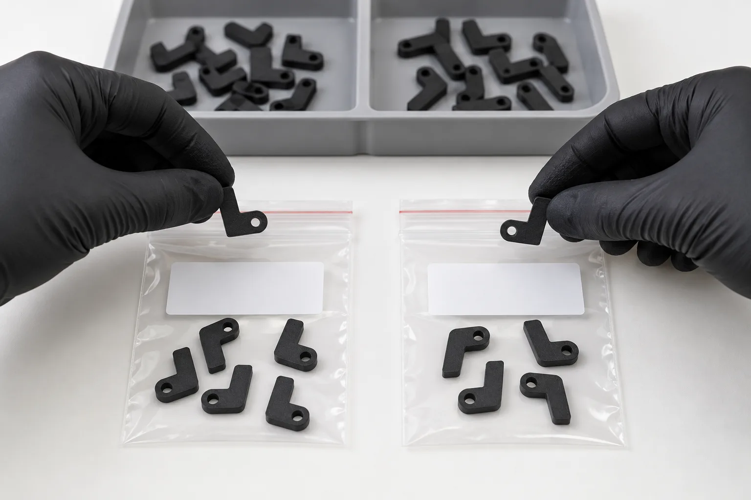
Left- and right-hand versions are separate parts: separate files, equal quantities and a bag for each.
Name the critical feature on the order
A drive component's order note identified the torque-transmitting bore for inspection. Naming the functional feature tells finishing and inspection where to look among the part's other surfaces.
DrawingsReading a Drawing Written for Another Process
The wire clip's drawing mixes requirements a powder-bed part can meet with notes written for something else. It calls for black TPU with a minimum Shore A hardness, sharp edges broken to a small minimum radius, and model-based definition, with undimensioned features taken from the 3D model. All three translate directly to SLS. It also carries tight general tolerances and printing notes written for an FDM printer. A powder bed needs no supports or infill settings and builds every part fully solid, so notes like these describe a different process.
Agree which tolerances govern
A small feature can be governed by the process's minimum tolerance band even when a drawing shows more decimal places. Check the quoted tolerance for the selected TPU grade rather than carrying over PA12 or machining tolerances. A drawing written for machining or moulding is not a printing specification unless both sides agree it is. Settle which tolerances govern before production starts, or note on the order that printed tolerances are accepted. If a printed part must meet a drawing's own tolerances, say so on the order and agree the inspection plan before the first lot is built. Our guide to reconciling drawings for additive manufacturing covers this in more depth.
Write elastomer specs as minimums
On your own drawings, state an elastomer as a property minimum, such as a Shore A minimum, rather than a single trade name, so the supplier can propose an equivalent powder-bed grade for your approval. Small elastomer parts often push wall limits, so run a wall-thickness check before a design freezes and bring thin walls up to our SLS design guide minimums: 0.8 mm where a wall is supported and 1.5 mm where it stands free. Where a thin feature must stay thin, give it a generous tolerance or a functional check rather than a two-place dimension.
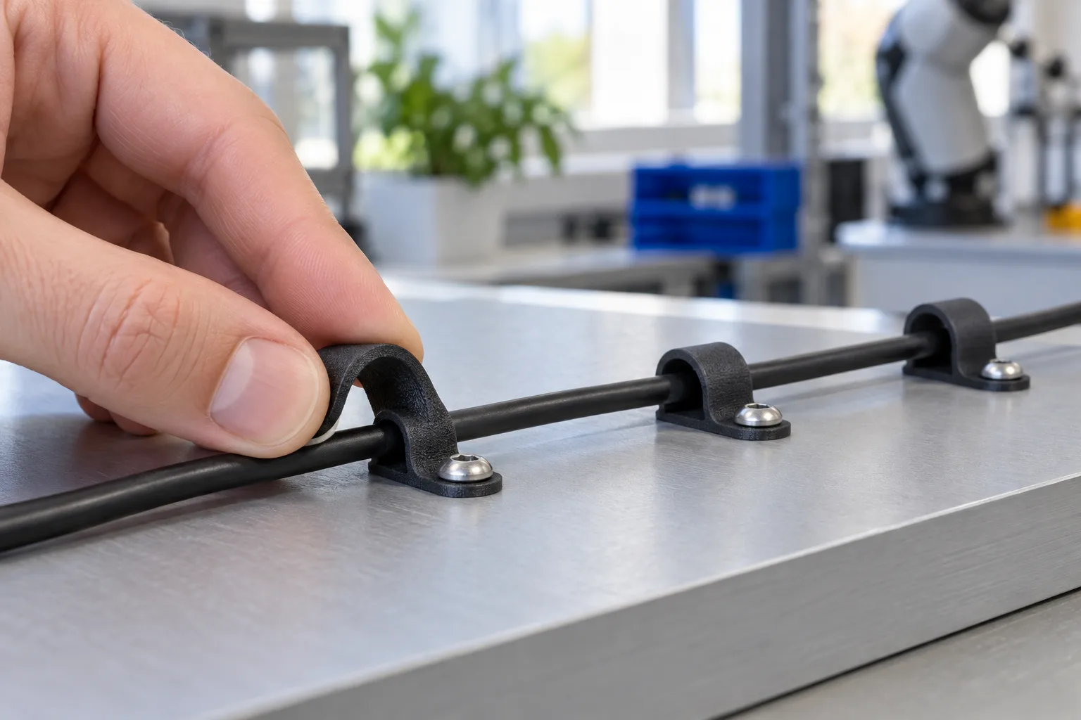
A flexible TPU cable clip prints in one piece, with no supports to remove.
Housing Revisions, Drive Ratios and Printed Tooling
Development parts and tooling can run alongside production while released production files remain fixed.
Revise the housing without changing production parts
Housing revisions were ordered as small SLS PA12 sets, each defined by a new file. Check a housing's longest dimension against the machine's bed before the design freezes. Long, shallow SLS parts also need time to cool in the powder cake to limit warping, so pulling a date forward is a scheduling decision more than a question of machines.
Ribs cost almost no extra material in SLS
The latest version of one half fills its interior with a dense, cross-hatched rib grid: about a quarter more surface area than the earlier design for less than 2% more volume. The measured volume is the point: SLS price follows sintered volume and build space, and this grid added surface while leaving both almost unchanged. What it does add is surface to depowder and dye. Our SLS design guide suggests ribs about as thick as the wall they support, or up to 0.5 mm thinner, and recommends supported walls of 0.8 to 1.0 mm. Fine rib grids push minimum feature sizes, so check them against the guide before the design freezes.
Trading material for lead time
A fit-check housing was switched from glass-filled to standard PA12 to meet the required schedule, allowing the team to check how the housing assembled. For a working housing, glass-filled PA12 adds stiffness: broad faces and mounting points resist bending more under the same load. Standard PA12 is lighter and allows more flex. The choice depends on whether the housing needs to stay rigid around its mounts or accommodate some movement during assembly.
A drive-ratio trial and printed tooling
Small quantities of drive variants can test alternatives while production continues from a released file. Printed tooling supports the same workflow: SLA split moulds in Accura 25 for low-volume overmoulding, SLS PA12 test fixtures and FDM ABS assembly jigs were supplied alongside the parts. A printed mould needs enough stiffness at the pour or cure temperature to hold its cavity shape under clamping pressure. Matching the resin to those conditions helps preserve the dimensions of the overmoulded part.
ResultsDelivery and Results
- Volume without tooling: small actuator components supplied in repeat lots without dedicated production moulds.
- Repeat lots from frozen files: handed stops, clamp plates and drive components reordered from released files.
- Speed: a median of five business days from order to ready.
- Development alongside production: housing revisions, drive trials and printed fixtures supplied without altering the released production files.
What to Apply to Your Own Actuator Parts
Key Takeaways
- Freeze the file, not just the part number. Reorder from the byte-identical file so every lot is built from the same geometry.
- Ask for the same orientation every lot. PA12 properties depend on build direction; fixing the orientation removes one source of variation between lots.
- Treat handed parts as two parts. Separate files, equal quantities, both hands in the same build, and bags marked by part number.
- Let fingertip-sized parts share builds. A lot of hundreds fits one compact build with no mould, and cooling and finishing, not just printing, set the lead time.
- Test alternatives beside production. A handful of printed pulley sizes tested other drive ratios without touching the production file.
- Put the critical feature in the order note, such as "inspect the non-round drive bore".
- Know which tolerances govern. Settle them before the first lot, or accept printed tolerances on the order.
- Write elastomer specs as minimums, such as "Shore A minimum", so equivalent powder-bed TPUs can qualify with your approval.
- Trade material for lead time consciously on fit-check parts, and check the envelope against the bed before the design freezes.
Could Your Actuator Parts Be Made This Way?
Good candidates are small, detailed parts ordered in dozens to hundreds at irregular intervals, such as stops, spacers, clamp plates and cable clips, plus the housings and test fixtures of a design still in development. SLS PA12 suits small, ductile structural parts. Glass-filled PA12 is stiffer and is the nylon to choose where wear matters. For flexible clips and bumpers, powder-bed TPU forms hooks, channels and screw seats in one piece.
See our SLS design guide, our guide to part orientation and 3D printing for robotics, and our case studies on humanoid robot hand parts in SLS PA12, heat-set inserts in an SLS PA12 sensor kit and repeat SLS PA12 production without tooling.
Running Small Robot Parts in Repeat Lots?
Send us your files, drawings and typical lot sizes. We will recommend a process and material for each part and set them up for repeat orders, including handed pairs and multi-part kits. Lead times start at 2 business days, 24-hour turnaround is available on request, and we offer next day shipping anywhere in the US and Canada.
Discuss Your Parts With Us