Technology OverviewDesign Guidelines

Selective Laser Sintering3D Printing Design Guidelines

Our Selective Laser Sintering (SLS) design guidelines help engineers and designers improve part quality, lower costs, and speed up production. Whether for prototypes or end-use parts, these best practices ensure strong, accurate SLS components with excellent surface finish and dimensional stability.

Quick Specifications

Build Volume
340 x 340 x 600 mm(13.4 x 13.4 x 23.6 in)
Tolerance
±0.25%, Lower limit of ±0.25 mm
Layer Height
60 - 120 Microns
Machinery
EOS P396
Selective Laser Sintering 3D Printer
Support-Free Printing
Complex Geometries

Quick Navigation

Overview

Selective Laser Sintering (SLS) is a powder-based additive manufacturing process that enables the production of strong, detailed parts without support structures. This freedom allows for complex geometries, internal features, and interlocking assemblies — but achieving optimal results depends on thoughtful design.

These SLS design guidelines outline the critical considerations for part orientation, wall thickness, tolerances, and material behavior. Following these best practices ensures your parts are manufacturable, cost-effective, and meet performance expectations in both prototyping and production scenarios.

Maximum Build Volume

Maximum Build Volume

340 x 340 x 600 mm (13.4 x 13.4 x 23.6 in)

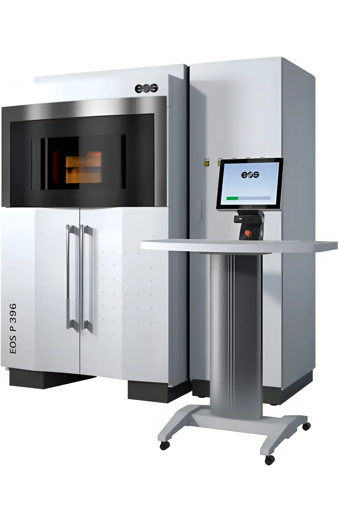
Our EOS SLS machines (EOS P396 and EOS P110 Velocis) offer a maximum build volume of 340 x 340 x 600 mm (13.4 x 13.4 x 23.6 in), allowing for the production of both small, intricate components and large, durable parts. They operate with a standard layer thickness of 100 µm, ensuring fine detail resolution while maintaining efficiency.

!

Parts designed with large flat planes will likely warp, so this should be avoided if tight tolerances are required.

Tolerances

Tolerances

Nylon PA 12: ±0.25%, with a lower limit of ±0.25 mm

If your parts require specific tolerances, please include an engineering drawing along with the part. Parts designed with large flat planes will likely warp, so this should be avoided if tight tolerances are required.

i

Tolerances differ for TPU: 0-30 mm (XY: ±0.35 mm, Z: ±0.90 mm), 30-50 mm (XY: ±0.40 mm, Z: ±1.15 mm), 50-80 mm (XY: ±0.50 mm, Z: ±1.50 mm)

Layer Height

Layer Height

60 - 120 Microns

The layer height is the overall Z resolution of the part; we avoid stepping artifacts on important features of your models by orienting the part(s) along the Z plane or at a 20 degree angle on all sides. Our EOS SLS printers (P396 and P110 Velocis) support layer heights of 60 µm, 100 µm (standard), and 120 µm, allowing for a balance between detail and print speed. Lower layer heights produce finer details and smoother surfaces but increase print time, making them ideal for precision components.

Surface Finish

Surface Finish

Uniform, Matte

SLS parts feature a uniform, matte finish with a fine, powdery texture, making them ideal for functional prototypes and end-use applications. The self-supporting nature of SLS eliminates the need for support structures, ensuring consistent quality and design freedom without post-removal marks. The surface is naturally durable and can be further enhanced through bead blasting, tumbling, or vapor smoothing for a refined aesthetic and improved performance.

Wall Thickness

Thicker geometries and walls with variable thickness are at risk of deformation due to shrinkage and stress. In general, follow wall design rules for injection molding to achieve a more uniform and consistent part.

Minimum Wall Thickness

Minimum Wall Thickness

0.8 mm - 1.0 mm (0.031" - 0.039")

Supported walls, which are connected on at least two sides and thick enough to support the model, require a minimum thickness of 0.8 mm (0.017"). For optimal strength and durability, we strongly recommend 0.8 mm – 1.0 mm to ensure sufficient rigidity and structural integrity.

!

Walls thinner than 0.45 mm may experience over-sintering, where excess laser energy causes unintended thickening, leading to loss of detail and potential warping.

Minimum Unsupported Wall Thickness

Minimum Unsupported Wall Thickness

1.5 mm (0.059")

Unsupported walls are those extending freely without additional support—a minimum thickness of 1.5 mm (0.059") is required to maintain structural stability. Thinner unsupported walls are prone to warping, bending, or breaking due to thermal stresses during the sintering process.

Recommendations:

  • Design unsupported walls with sufficient thickness
  • Incorporate structural reinforcements like ribs or fillets where possible
  • Ensure dimensional accuracy and mechanical strength
Minimum Pin Diameter

Minimum Pin Diameter

0.8 mm (0.031")

Freestanding features such as pins require a minimum diameter of 0.8 mm (0.031") to ensure structural integrity and printability. Pins below this threshold may become fragile, prone to breakage, or fail to print accurately due to the sintering process and powder removal.

Recommendations:

  • Thicker pins provide better mechanical strength and durability
  • Consider adding support structures for smaller pins
  • Increase the base connection to improve stability

Minimum Detail

The quality of engraved and embossed features depends heavily on part orientation and the resulting thermal effects of printing. It is best to orient text or other small details facing down on the XY plane, or oriented vertically on the ZX or ZY plane (though layer height will limit resolution).

Engraved Details

Engraved Details

Minimum Width and Depth: 0.5mm (0.019")

Engraved details are recessed features designed into a model, requiring a minimum width and depth of 0.5 mm (0.019") to ensure clarity and visibility. Features smaller than this may become partially or completely filled with unsintered powder, leading to closed gaps and loss of detail during post-processing.

Recommendations:

  • Maintain sharp edges and legibility
  • Consider increasing depth for better visibility
  • Use bold, well-defined shapes for enhanced readability
Embossed Details

Embossed Details

Minimum Width and Depth: 0.5mm (0.019")

Embossed details are raised features on a model, generally resolving better than engraved details due to their prominence above the surface. To ensure clarity and definition, embossed details should have a minimum width and depth of 0.5 mm (0.019").

i

Extruded text requires at least 1.5 mm (0.059") thickness when printed flat and 2 mm (0.079") when printed vertically to maintain legibility.

Text Size

Text Size

Minimum point size: 14pt

For legible and well-defined text, a minimum line thickness and depth of 0.5 mm (0.019") or a minimum font size of 14pt is recommended for all orientations. Text smaller than this may lose sharpness, become illegible, or blend into the surface.

Recommendations:

  • Opt for bold, sans-serif fonts with adequate spacing
  • Serif fonts may require larger sizes for clarity
  • Increase depth for better definition

Part Clearances

The mechanical performance of printed assemblies is sensitive to variables such as print orientation, layer height and machine tolerances. It is best to test and refine any mated parts before committing to a full production run.

Minimum Clearance

Minimum Clearance

0.5mm (0.019")

Clearance refers to the gap between moving or interlocking parts, such as hinges, joints, and mating components, ensuring they function properly without fusing together during printing. A minimum clearance of 0.5 mm (0.019") is required to prevent parts from sintering together.

!

Insufficient clearance can lead to tight fits, difficulty in assembly, or complete bonding of parts, while excessive clearance may cause looseness or instability.

Minimum Press Fit

Minimum Press Fit

0.1mm (0.004")

For a secure press fit, a minimum offset of 0.1 mm (0.004") is recommended to allow parts to fit together tightly without requiring adhesives or fasteners. Adding a chamfer or slight taper at the leading edge helps guide the parts into place more smoothly.

Recommendations:

  • Print a test part to validate tolerances before full production
  • Consider material properties and post-processing effects
  • Ensure strong, repeatable connections
Hinges & Mechanical Linkages

Hinges & Mechanical Linkages

Minimum: 0.6 mm (0.023")

SLS 3D Printing allows for the printing of fully assembled mechanical linkages, such as hinges, chains, and moving joints, in a single build without the need for assembly. To ensure free movement and prevent parts from fusing together during sintering, a minimum clearance of 0.6 mm (0.023") is required.

Recommendations:

  • Round contact points and add fillets
  • Test fitment with small prototypes
  • Consider powder fusion and heat exposure effects

Holes & Gaps

As a part is sintered, hollow features end up filled with powder which must be removed in post processing. Make sure to design parts with powder removal in mind, and avoid long winding channels, which cannot be cleared.

Minimum Hole Size

Minimum Hole Size

Sensitive to wall thickness

Minimum hole diameter varies based on wall thickness to ensure proper powder removal and dimensional accuracy.

Wall ThicknessMinimum Hole Diameter
1mm (0.039")0.5mm (0.019")
3mm (0.11")0.6mm (0.023")
6mm (0.22")0.7mm (0.027")
Minimum Gap Size

Minimum Gap Size

Sensitive to wall thickness

Minimum gap size varies based on wall thickness to ensure proper powder removal and prevent fusing.

Wall ThicknessMinimum Gap Diameter
1mm (0.039")0.5mm (0.019")
3mm (0.11")0.6mm (0.023")
6mm (0.22")0.7mm (0.027")
Minimum Escape Hole Size

Minimum Escape Hole Size

4 mm (0.157")

Escape holes are essential for removing unsintered powder from hollow or enclosed parts. A minimum hole diameter of 4 mm (0.157") is required when using a single escape hole to allow efficient powder removal.

💡

For larger parts exceeding 50 mm x 50 mm x 50 mm, at least two escape holes are recommended, each with a minimum diameter of 2 mm (0.078").

Part Geometry

Part geometry can be optimized for 3D printing to reduce material usage, increase strength and rigidity, and take advantage of machine capabilities.

Fillets

Fillets

Recommendations for SLS 3D Printing

Fillets are smooth, rounded transitions between surfaces that help reduce stress concentrations, improve part strength, and enhance durability, especially in load-bearing or high-stress areas. Sharp corners can act as weak points where stress builds up.

Recommendations:

  • Align fillets with a common center point to maintain consistent wall thickness
  • Consider gradual fillets instead of abrupt transitions
  • Use fillets to aid in powder removal and improve surface quality
Bosses & Ribs

Bosses & Ribs

Recommendations for SLS 3D Printing

Bosses and ribs are structural reinforcements that enhance strength, stiffness, and durability while keeping material usage efficient. These features are particularly valuable in thin-walled or load-bearing components.

Recommendations:

  • Bosses and ribs should generally match the part thickness or be up to 0.5 mm less
  • Use ribs to support tall, thin, or unsupported structures
  • Design bosses as mounting points for fasteners and inserts
Support Structures

Support Structures

Selective Laser Sintering 3D Printing

SLS does not require support structures since parts are fully supported by the unsintered powder in the build chamber. This allows for complex geometries, overhangs, and internal features without additional material or post-processing to remove supports.

💡

Freedom in design enables lightweight, intricate, and fully functional parts with minimal post-processing.

Infills

Infills

Selective Laser Sintering 3D Printing

Unlike FDM, SLS parts are always produced with solid walls, as the process does not use variable infill patterns. The entire part is built with fully sintered material, ensuring consistent mechanical strength, durability, and density.

i

Hollow sections can be designed with escape holes to remove unsintered material, reducing weight without compromising structural integrity.

Threads & Inserts

Threads and inserts can increase functionality of your parts, but keep in account that printed threads will wear down through repeated cycles of assembly and disassembly, while heat set inserts can potentially deform or cause imperfections on part finish due to the heat processes of installation.

3D Printing Threads

3D Printing Threads

Selective Laser Sintering

For functional, reliable threading, we recommend using M6 thread sizes or larger and employing thread profiles designed for plastics to accommodate the unique properties of SLS-printed parts.

Recommendations:

  • Use an offset of 0.5 mm to compensate for thermal shrinkage
  • Consider heat-set or machined metal inserts for smaller or high-wear threads
  • Account for naturally rough surface texture that increases friction
Tapping & Threading

Tapping & Threading

Selective Laser Sintering

For strong, functional threads, parts should be designed with holes sized for tapping or center marks for drilling pre-tapped holes. Ensure sufficient wall thickness is maintained around tapped holes, especially in load-bearing areas.

i

Unlike FDM, SLS prints are isotropic, meaning layers bond more uniformly, reducing the risk of thread delamination.

Threaded Inserts

Threaded Inserts

Selective Laser Sintering

Threaded inserts can be glued in or heat-set for stronger, more durable connections. Heat-set inserts require a soldering iron with an installation tip, which softens the plastic walls as the metal insert is pressed in.

Recommendations:

  • Boss diameter should match the maximum diameter of the insert
  • Factor in thermal shrinkage for secure fit
  • Add chamfer or fillet around boss edge to guide insert placement

Post Processing

While printed parts are highly functional and accurate, there are a variety of ways to modify them after printing to enhance durability or aesthetics.

Sectioning, Joining, and Bonding

Sectioning, Joining, and Bonding

Selective Laser Sintering

For parts larger than the build volume, designs can be split in CAD and printed in multiple sections, then glued, press-fit, or mechanically joined. Adding alignment features like tongue-and-groove joints ensures precise positioning.

Recommendations:

  • Consider material properties, print orientation, and potential shrinkage
  • Print a small test piece to fine-tune tolerances
  • Plan sectioning to maintain structural integrity
Post-Machining

Post-Machining

Machining SLS Parts

SLS-printed parts can be machined using traditional or CNC equipment to achieve tighter tolerances, smoother surfaces, and precise fitments. This is particularly useful for critical features such as bearing surfaces, threaded holes, or mating components.

Recommendations:

  • Add extra material (machining stock) to surfaces that will be machined
  • Plan fixturing and part orientation to minimize warping
  • Consider milling, turning, or grinding for high-precision applications
Coatings

Coatings

Selective Laser Sintering

SLS parts are naturally white when printed but can be dyed black for a uniform appearance. Additional coatings, such as lacquers, varnishes, or clear coats, offer custom finishes while enhancing durability and performance.

Recommendations:

  • Improve wear resistance, UV stability, and surface hardness
  • Enhance water tightness and prevent marks and smudges
  • Consider professional coating for production-ready finish
Vapor Smoothing

Vapor Smoothing

Selective Laser Sintering

Vapor smoothing is not applicable for Selective Laser Sintered parts.

i

Other post-processing methods like bead blasting or tumbling can be used to improve surface finish.

Ready to Start Your Selective Laser Sintering Project?

Upload your design and get an instant quote optimized for selective laser sintering manufacturing.

Click to start your quote

STL, STEP, OBJ, 3MF supported • Get instant pricing

6
Industrial 3D Print Technologies
50+
Plastics, Resins & Metals