

A robot hand needs more than strong finger links. It also needs contact surfaces that grip, covers that protect moving parts and cable guides that fit into a small space. Forge Labs has made these components for multiple humanoid-robot developers, using SLS PA12, PolyJet and SLA from early samples through repeat batches.
The examples below come from different hand designs. In one, revised SLS finger segments used about 40% less material while separate grip pads let the team test hardness and texture. Other work included protective shells, wrist housings and covers specified with rigid and flexible regions. Together, they show how to choose a process for each part and move useful design changes into the next build without making a mould.
Parts and MaterialsChoose the Process for the Part's Job
A finger link carries load; a pad makes contact; a cover keeps surrounding hardware clear of moving parts. Giving all three the same material would compromise at least one of those jobs. In the first hand design, the structure was black SLS PA12, the grip pads were a black rubber-like PolyJet material, and thin white SLA Accura 25 plates provided a rigid base for the pads. Other hand and wrist assemblies used PA12 for shells, frames and small cable-management parts.
| Part family | Process and material | Manufacturing advantage |
|---|---|---|
| Finger segments, palm plates and wrist interfaces | SLS PA12 | Small structural features, ribs and open pockets without support structures; new revisions need no new tooling |
| Protective shells, wrist housings and cable guides | SLS PA12, natural or dyed | Curved walls, mounting features and left/right versions in small batches |
| Separate grip pads | PolyJet rubber-like material | Hardness, contact shape and surface texture can be trialled independently of the frame |
| Rigid pad backing plates | SLA Accura 25 | A smooth, thin support for a replaceable contact surface |
SLS is useful here because the surrounding powder supports the parts. Bores, slots and webs need no support structures, mould draft or support-removal marks. Small components can share a build, and left- and right-hand versions can run together without separate tools. Quantities can follow the next assembly build: a handful of a revised part, or a few hundred of a released design.
Material properties still need to match the load. EOS reports 48 MPa tensile strength and 18% elongation at break in X/Y for PA 2200, compared with 42 MPa and 4% in Z. Our PA12 data lists a fatigue strength of 22 MPa at 10⁷ cycles. Those are material-test values; use them to plan orientation and testing, rather than treating them as a load rating for a printed finger. Thin webs and lugs should be oriented with their bending loads in mind.
Our standard SLS PA12 tolerance is ±0.3%, with a ±0.3 mm minimum; the minimum governs on parts under 100 mm. The original finger-part orders did not request tighter tolerances. Where a pin fit needs more precision, identify that bore before quoting so reaming or machining can be included as a secondary operation.
Finger StructureRemove Material Where It Makes a Difference
In the first hand design, a comparison of two released CAD revisions found about 40% less volume in each of the two main finger segments at essentially the same outside size. This is a measured change in CAD volume, not a physical weight or strength test. Many smaller nylon parts changed little; most of the reduction came from a few larger structural components.
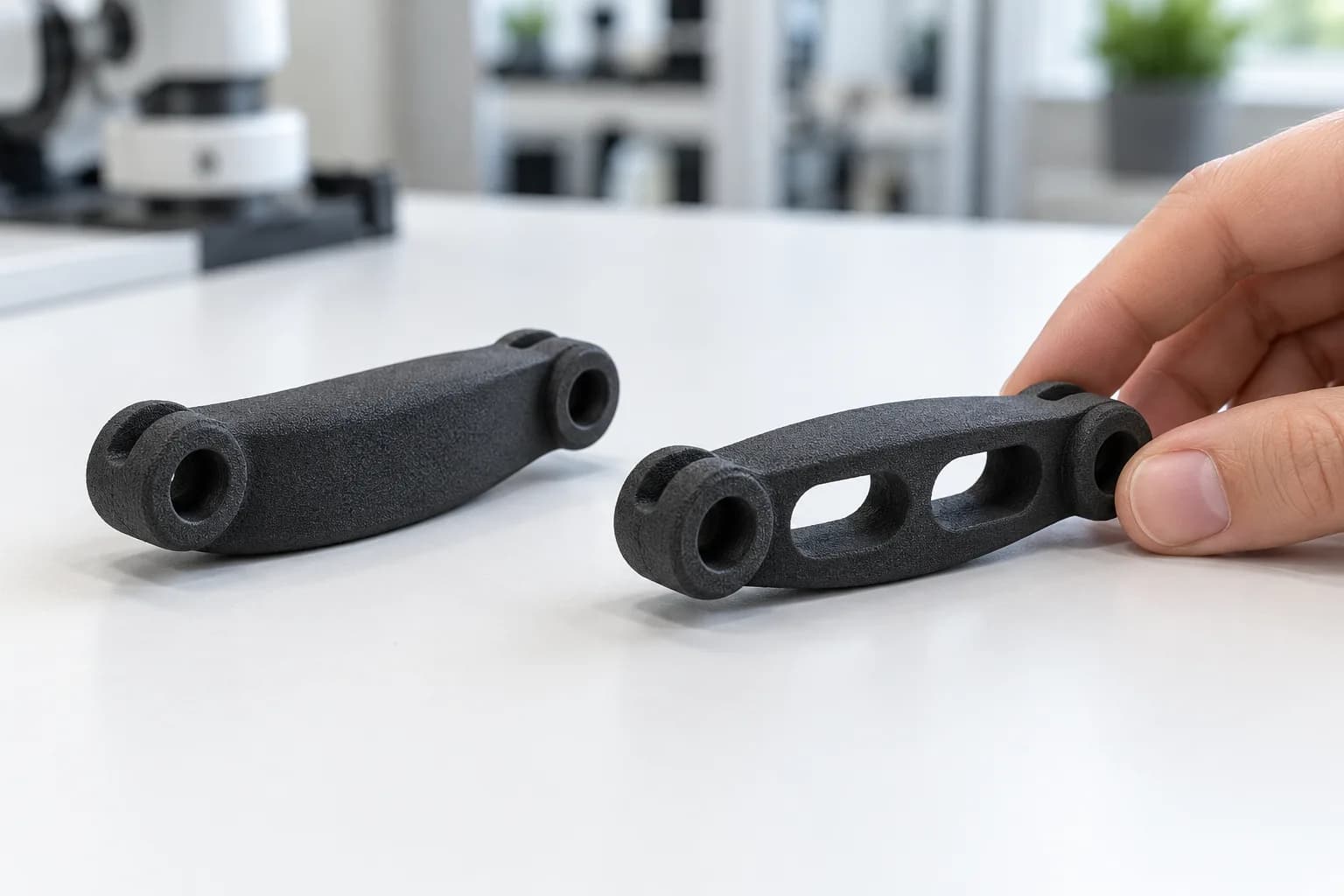
Open pockets remove material from a finger segment while leaving room to preserve its mating features.
Counting only components common to both revisions, the later design used about a quarter less nylon per hand. About nine-tenths of that saving came from a small group of larger parts. That is a useful way to prioritize redesign: multiply each part's volume by its quantity in the assembly before deciding where to spend engineering time. Halving a tiny clip may save less than a modest reduction in a palm plate.
Removing material can help both motion and manufacturing cost. The actuators have less material to move, while SLS pricing is influenced by sintered volume and the space occupied in the build. Extra ribs or pockets do not each require a separate machining operation. Keeping the outside envelope and mating features stable can also contain the redesign, although the interfaces still need to be checked directly; matching overall dimensions alone does not prove that every bore stayed in place.
The useful limit is stiffness and load path, not the largest possible percentage reduction. Keep material around pin bores, bosses and loaded faces, then remove it from less heavily loaded areas. A finger with less material may deflect more under the same grip force, so the revised part needs to be checked under its intended load.
- Give powder a way out. Open windows are easier to depowder than sealed hollows. Our SLS design guide asks for an escape hole of at least 4 mm when a single hole is used; see also our guide to hollowing parts.
- Keep walls printable. The guide sets a 0.8 mm minimum for supported walls, with 0.8–1.0 mm recommended, and 1.5 mm for unsupported walls. A thin cable clip needs this check just as much as a large finger segment.
- Check the assembly again. Confirm clearance, pin fits and deflection on the revised part before releasing the next larger batch.
Develop the Grip Without Redesigning the Hand
The first hand used separate PolyJet pads on SLA backing plates. Pad texture and contact shape could change while the nylon structure stayed in place, and pad variants could be ordered without duplicating every frame component. This also made it possible to compare softer and firmer versions of the same pad geometry rather than changing shape and hardness at the same time.
A small hardness trial, supplied with backing plates, shipped in two business days. Its value was the controlled comparison: the team could evaluate the contact material against the same supporting geometry. For your own trial, decide whether you are testing hardness, surface texture or shape, and hold the other variables steady. Record the selected blend, glossy or matte finish and support style on subsequent orders so the comparison can be repeated.
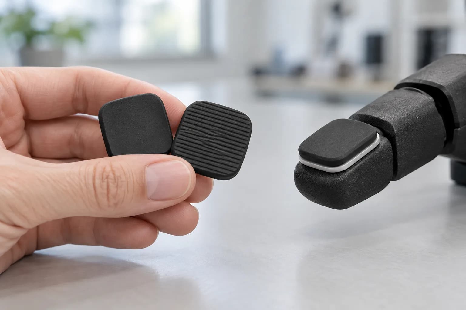
Separate pads and backing plates let the contact surface change while the surrounding structure stays in place.
The backing plate has its own job. Accura 25's tensile strength of 38–41 MPa and tensile modulus of 1,400–1,600 MPa suit a thin, rigid base beneath a soft pad. Its heat deflection temperature is 50–60 °C at 0.45 MPa, so check the margin near warm motors. Specify which face may carry SLA support marks to keep the pad seat clean.
When rigid and flexible regions share a cover
A separate cover design took a different approach: the order specified VeroClear for a rigid body and Agilus30 for a flexible region in the same multi-body STEP file. A material list assigned each body to its resin, and that instruction accompanied the order to the shop. The useful lesson is in defining the part: a single material selection cannot communicate which region should be rigid and which should flex.
Multi-material PolyJet can combine rigid and rubber-like regions in one print. Keep the regions as separately identified bodies, supply the material assignment, and resolve overlaps before manufacture. That is a different design choice from a removable pad on a backing plate: the removable arrangement makes contact-surface changes easier, while integrated regions put the material boundary into the part definition.
For new pad development, Agilus30 is one available rubber-like material; Forge's data lists 240% elongation and 3.1 MPa tensile strength. Blending it with a rigid resin produces firmer grades. Stratasys positions it for design validation and prototyping, so test the selected blend for wear before relying on it for long service. Our PolyJet guide calls for at least 1.0 mm walls in flexible materials such as Agilus30. Check the flexible layer itself, not just the combined thickness of a rigid carrier and soft surface.
Covers and RoutingBuild the Covers and Cable Guides Around the Mechanism
Other humanoid-hand work used SLS PA12 for curved finger and thumb shells, open palm frames, wrist housings and small cable-management parts. These were a separate set of designs from the lightened finger links above. Screw seats, slots, clips and mounting features were built into the geometry, allowing each part to fit around the mechanism without making a dedicated mould.
The order history includes a smaller shell batch followed by a batch more than twice its size, along with later wrist parts. Some designs were repeated while others changed. That is a practical advantage during development: a cover, cable guide or mounting panel can be revised independently, and the next order can contain a mixture of new and already released parts. It does not require treating every reorder as a redesign of the whole hand.
Left- and right-hand parts need clear identification even when they look alike. Give each handed version its own file and part number, and set the quantity needed for that side. Do not assume equal quantities or treat every apparent mirror as interchangeable. A modelled part ID can help keep small shells and clips identifiable through cleaning, finishing and packing.
Revision checks also need more than a filename. Exporting a part in a different orientation changes its bounding box without changing its shape. Compare aligned geometry and the features that matter to assembly; volume and surface area are useful screening checks, but matching totals do not establish identical geometry. Keep the native STEP file where possible, use a consistent format between orders, and say when a re-sent file has only been renamed or re-exported.
Finishing belongs in that definition too. SLS PA12 prints natural white; Forge dyes black parts in-house on DyeMansion equipment, with no additional standard production days for black. Put the required finish on every order rather than relying on the filename or the appearance of a CAD preview. For a custom colour, agree the colour reference and finishing requirement before the batch is scheduled.
Manufacturing and DeliveryPlan Samples, Inspection and Repeat Orders Together
Forge offers manufacturing lead times from two business days, with 24-hour turnaround on request. The useful question for a robot build is which parts can be ready together: a small pad trial, a first set for fit checks, or a complete kit across several processes. The two-day pad trial above is one completed example. Larger kits need a schedule that accounts for printing, cooling, finishing and any agreed inspection, as well as shipping to your assembly team.
Completed orders give a more useful picture than print speed alone. These examples measure business days from order submission to final dispatch, excluding carrier transit:
| Work supplied | Batch scale | Order to final dispatch |
|---|---|---|
| Grip pads with backing plates | Small hardness trial | 2 business days |
| PolyJet covers | About 100 parts | 5 business days |
| SLS cable guides and support parts | More than 100 parts | 6 business days |
| SLS shells and trims | More than 100 parts | 8 business days |
| SLS wrist parts, clips and trims | A few dozen parts | 4 business days |
These are completed examples from different orders, not one standard lead time for every part. A usable assembly set may be needed before the complete batch, while a first-article check may need to happen before the remaining quantity is released. Put those milestones into the quote so the manufacturing schedule reflects the build you need to complete.
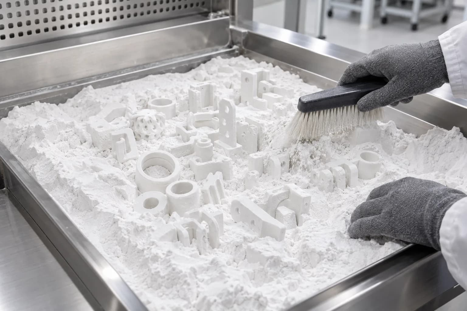
Small nylon components can share a powder bed, supporting sample quantities and larger repeat batches without a dedicated tool.
The reviewed hand work grew to thousands of components across SLS, SLA and PolyJet. Small nylon parts shared compact builds with other work, and quantities were set for each design. After printing, SLS parts need cooling and depowdering; PolyJet parts need support removal; SLA plates need support removal and UV post-curing. Printing is one step in that sequence, so a machine finishing its run is not the same as a kit being ready to ship.
Use the first sample to settle the production requirements
On a separate robotics cable-management order, each line called for a first article, and the SLS build allocations began with one of each design before the larger quantities. This is a useful way to fit sampling into the manufacturing plan: small parts can share a build, so an initial sample need not fill an entire machine on its own.
Agree the sample quantity, controlling CAD revision and acceptance checks before the order runs. For a finger link, that may mean pin fit, clearance and deflection under load; for a cover, mounting-hole alignment and clearance around moving hardware. Define who accepts the sample and when the remaining quantity can be released. Retain the approved material, finish and build requirements with the repeat order. Record the inspection and approval with the released revision so the next order starts from the accepted part.
Ship a useful subset when the full kit takes longer
Some larger hand kits were shipped in stages by process. This can help assembly start earlier if the first shipment contains parts that can actually be used together. Identify that subset when ordering: for example, the complete set needed for a fit check, with its handed parts and matching backing plates. Then schedule the remaining components around the agreed production and finishing steps.
Once a design is released, repeat quantities can come from the same files without new tooling. Keep the revision, material, pad blend, finish and handed quantities explicit on the reorder; change only what the next build needs. That is what makes additive manufacturing useful beyond the first prototype: the same ordering route supports a small experiment, a corrected part and a larger repeat batch.
Plan Your Next Robot Hand Build
Send the CAD for the structure, contact surfaces and covers, along with the quantities and the checks needed before a larger batch. We can recommend a process for each part and plan samples, finishing and repeat orders around your assembly needs. If a part sees repeated sliding contact, glass-filled nylon is another SLS option to consider for wear resistance.
For design rules, see our SLS, PolyJet and SLA guides. Related examples include wearable robotics actuator parts, an SLS PA12 subsea electronics chassis and repeat production without tooling.
Discuss the next build with our team. Lead times start from two business days, with 24-hour turnaround on request and next-day shipping across the US and Canada.
Discuss Your Robot Parts With Us