
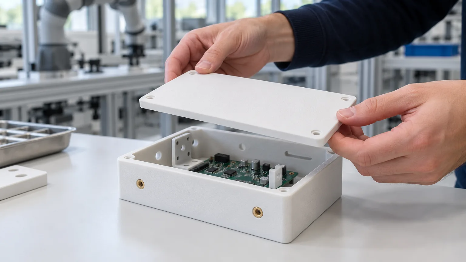
An enclosure is only useful when its lid, electronics tray and mounts fit together. Forge Labs printed these sensor components in SLS PA12 from prototypes through repeat production, with no tooling. M4 and M5 threaded inserts were specified across the kit, making consistent hardware selection and hole geometry central to the manufacturing plan.
This case study covers why SLS suited the kit, how light drawings located every insert, how the kit ran through the shop and what to put on an order so M4 and M5 inserts come out the same in every lot.
The Project at a Glance
- Application: sensor enclosure components supplied as matched kits from prototype to production without tooling
- Parts: a one-piece enclosure, lid, internal tray and sensor mounts
- Process: SLS, with parts sized to share builds
- Material and finish: Nylon PA12 in natural white or black, specified per part
- Inserts: M4 and M5 heat-set threaded inserts, with insert material and dimensions specified on the order
- Orders: prototype, pilot and repeat production lots, with revisions made directly in CAD
- Delivery: staged shipments matched by component so assembly could proceed with complete kits
An Enclosure Designed as a Kit
The enclosure prints as one piece with an open side closed by a separate lid. An internal tray carries the electronics, while separate mounts locate the sensor hardware. Keeping those functions in separate parts lets a mounting detail change without redrawing the whole enclosure.
The enclosure: features printed in, not machined
The enclosure carries connector ports, small holes and windows, hex pockets that capture nuts, mounting slots in the side walls and an internal rail. Our DFM analysis counted dozens of holes, many counterbored or countersunk. In a machined or fabricated box, each feature is a separate operation. In SLS they print with the walls, with no supports or draft, and none was ordered as a secondary operation.
The walls provide more material than the SLS minimum of 0.8 mm for supported walls and 1.5 mm for unsupported ones. A housing that is handled, screwed shut and fitted with inserts needs wall thickness set by those loads and the selected hardware, not by printability alone.
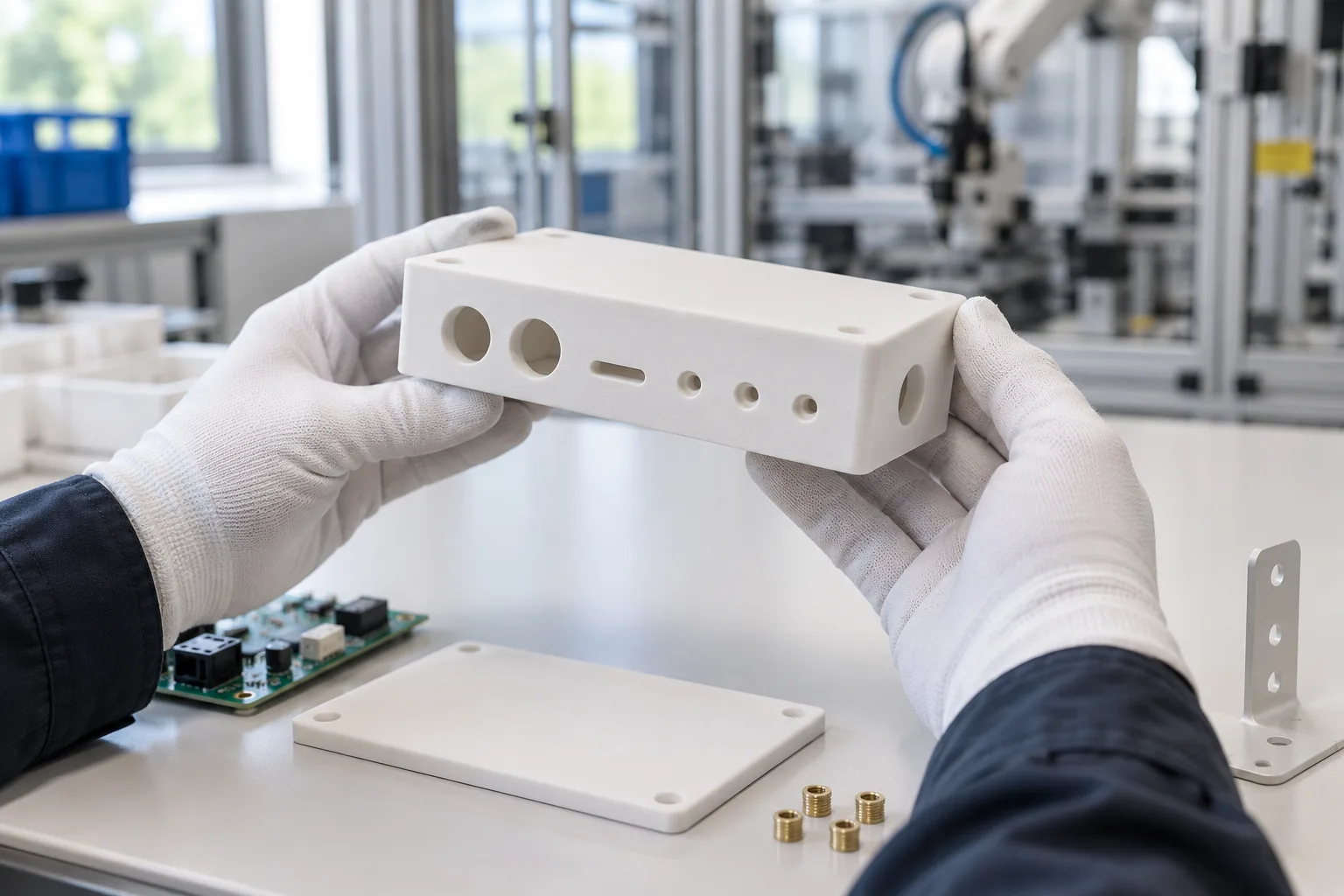
Ports, slots and counterbores print with the walls, so none of them needs a machining operation.
The lid, the tray and the mounts
The lid carries insert seats on its inner face. Raised features provide material around the inserts without thickening the entire cover.
The tray is drawn like folded sheet metal: a front plate with screw holes, counterbores, slots and a connector cut-out, and side plates with tall windows for cable routing. In sheet metal it would need cutting, bending and bend reliefs; in SLS PA12 it is one part with no bends, and no inserts. Some mounts also specify inserts; parts that do not need threaded joints can stay as printed.
Process ChoiceWhy SLS PA12 Fit the Whole Kit
- Revisions without tooling. Every part was printed from the customer's CAD, and changed designs went into the next lot as new files. A moulded enclosure with ports and pockets on several faces would typically need a tool with side actions, and each revision would have meant reworking tooling.
- A compact bed for every part. The enclosure and its smaller companion parts fit a compact SLS bed, giving production a choice of machines and shared builds.
- Metal threads for repeated access. PA12 softens around a heated insert and grips it as it cools. This gives the lid and mounts durable metal threads for assembly and servicing, with the insert seats printed directly into the parts.
- Tough, electrically insulating walls. PA12 suits housings that protect electronics and are handled during installation and servicing. Its toughness helps the enclosure and mounting features tolerate assembly loads, while its electrical insulation provides a nonconductive material around the circuit boards and connectors.
SLS PA12 prints in natural white, with an optional black finish applied in-house using DyeMansion equipment. Dye colours the nylon below the surface, keeping the finish thin around connector openings and mating features. Colour can be selected separately for the enclosure, lid and internal parts.
DrawingsHow Light Drawings Located Every Insert
The customer's 3D models defined the geometry, so the drawings had one job: show where the inserts go.
- Enclosure: ballooned views and a parts list locate the hardware.
- Lid: an underside view shows the insert positions that are hidden in the assembled kit.
- Mounts: a marked-up model view identifies the holes requiring inserts.
In our quoting portal, the customer also pinned each enclosure and lid insert on the uploaded drawings with markers tied to the line's insert specification. No document carried tolerances, datums, finish or colour notes, so every line used our standard SLS PA12 tolerance of ±0.3% with a ±0.3 mm minimum. Insert sizes and lengths lived on the order lines, not the drawings: thread and pitch, installed length, insert material, quantity per part and the maximum hole diameter for that insert.
The drawing and order need to agree. Here, CAD parts-list defaults named steel for nylon parts, and the drawing called out press-fit inserts while the order specified heat-set. A customer discussion resolved the insert specification. Catching that conflict before production is more useful than treating either document as automatically correct.
When the model defines the geometry, a light drawing is enough to locate inserts; the insert specification itself belongs on the order (see drawing reconciliation for 3D printing).
Threaded InsertsSpecifying M4 and M5 Inserts Across a Kit
Why inserts, and why heat-set
Heat-set inserts give the small M4 and M5 screws a durable metal thread, making it easier to open the housing for servicing and close it again securely. The nylon forms the enclosure and its mounting features, while the metal insert takes the wear from repeated fastening. Our SLS design guide covers hole design and thread options for these joints.
A barbed press-fit insert goes in cold and holds by interference as its barbs bite into the wall. A heat-set insert goes in hot: the nylon around it softens, flows into the knurls and solidifies again, so the part's own material locks the insert. In a thermoplastic such as PA12 that generally resists torque-out and pull-out better and tolerates small variations in hole size. Our SLS design guide notes that installation heat can mark the surrounding surface, so keep insert holes off cosmetic faces.
The insert specification
| Requirement | What to record | Why it matters |
|---|---|---|
| Thread | Size and pitch, such as M4 or M5 | Identifies the mating fastener |
| Insert body | Manufacturer or agreed specification, installed length and material | Sets the required hole geometry and installation method |
| Location | Marked positions and count per part | Distinguishes insert holes from plain or clearance holes |
| Hole | Diameter, entry shape and depth matched to the selected insert | Provides nylon for retention and space for displaced material |
Thread size alone does not define the outside of an insert. Different body lengths, knurls and materials can require different holes.
One hole size per insert specification
The models used consistent hole diameters for their M4 and M5 insert positions across the kit. That reduces the number of features to model and check, provided every position uses the same approved insert specification. Each specified insert carries its own hole limits; compare the model with those limits rather than assuming all inserts with the same thread need the same hole.
Holes drawn for a barbed press-fit insert are not automatically right for a heat-set insert, which usually wants a slightly undersized, often tapered hole so the melted nylon has something to grip. When the insert type changes, check every hole against the new insert maker's recommended size.
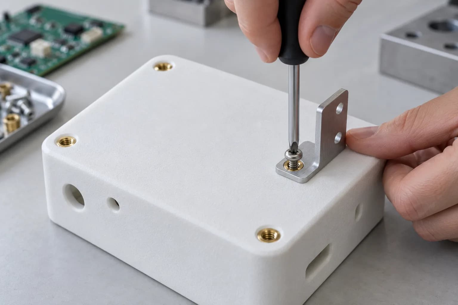
Standardize the hole around the selected insert specification, including its body size and installed length.
Match the hole depth to the insert
A heat-set insert needs a hole deeper than its installed length, so displaced nylon and the screw tip have somewhere to go. Check depth against the installed length of the selected hardware and the insert maker's guidance. Leave room for displaced material and the screw tip, and choose an insert length that suits the available wall rather than adding thickness by default.
Insert material, lot by lot
The order specifications included brass and stainless steel. Brass is the usual default for heat-set inserts in plastics: it conducts heat well, so it reaches temperature quickly and melts the surrounding nylon evenly. Stainless steel is chosen for corrosion resistance or to match stainless fasteners. It conducts heat far less well, so expect a longer installation cycle, and confirm the maker's hole size and installation settings for the stainless version rather than reusing the brass ones. Insert material is a field on each order line, so it can change from lot to lot and stays recorded against that lot.
Our quoting portal offers heat-set inserts on our SLS and MJF nylons and the main FDM engineering thermoplastics, in brass or stainless steel, metric from M1.6 to M10 and imperial from 0-80 to 3/8 in. You place each insert on your uploaded drawing, and inserts add two production days.
ProductionHow the Kit Ran Through the Shop
A kit spans more operations than the print itself. Keep each part's released file, colour and insert specification together, then plan the finishing and hardware work so the component quantities match at dispatch.
Revisions between lots, without tooling
Enclosure features, mounting details and the internal tray changed between lots. Each revision arrived as a new file, allowing the next build to carry the updated geometry without replacing a mould.
The largest change was to the tray. The plates were thickened, window ends rounded and internal radii opened up. The first revised trays shipped three business days after the new files arrived. Rounded window ends and a larger inside radius take stress out of sharp corners, and thicker plates add stiffness. In a bent-metal bracket that could mean new tooling or a heavier gauge; here it was an edit to the model. Where only some plates carry screws, thicken those and leave the rest as they are.
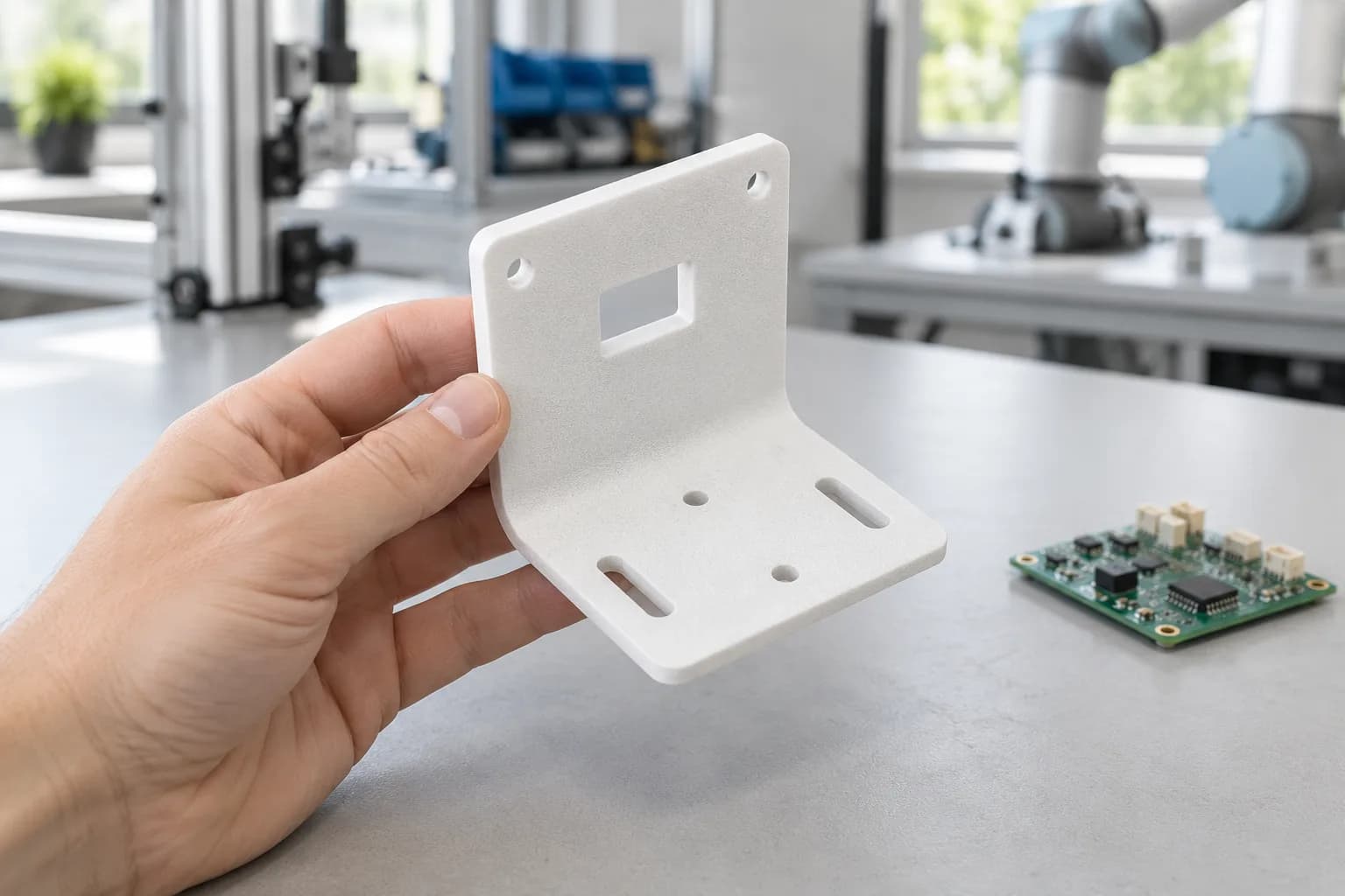
A bracket drawn as folded plate prints as one part, so thickening its plates between lots is a file change.
Kit-matched staged shipments
Staged shipments carried matched enclosure components so assembly could proceed with complete kits. A large lot can span many builds; specify the required component mix and delivery cadence on the purchase order so a shipment contains usable sets.
What the build records show
The reviewed repeat lot shared SLS builds with other work and ran across compact and larger machines. Parts that fit either build envelope give production more scheduling options. Printing is only one part of the schedule: cooling, depowdering, dyeing where specified and insert work also need to be planned.
Repeat orders copy one specific order
The kit was reordered through the portal's repeat function. A repeat starts from one specific past order's lines, including its file revisions and colours. When revisions or colours differ between past orders, say which order a repeat should copy, and check each line before you place it.
ResultsDelivery and Results
- From prototype to production: matched enclosure kits were supplied through prototype, pilot and repeat production.
- Inserts specified line by line: M4 and M5 hardware was specified by type, thread, installed length, material and count per part.
- Revisions without tooling: enclosure and tray changes went into subsequent lots as new files.
- Assembly-ready shipments: staged deliveries kept the component mix matched for complete kits.
- One process throughout: the enclosure kit stayed in SLS PA12 from prototypes through repeat orders.
What to Apply to Your Own Insert-Bearing Parts
Key Takeaways
- Specify the insert completely on every order: type, thread, installed length, insert material and count per part. Resolve any difference between the drawing and order before the lot runs.
- Standardize holes around an approved insert specification, including the insert body and installed length, not only the thread. When the insert type changes, recheck those holes against the new insert maker's recommendation.
- Model the hole deeper than the insert, following the selected hardware maker's guidance.
- Let a light drawing locate the inserts, and put the material on the order. A ballooned view or a marked-up screenshot was enough; CAD parts lists default to materials such as steel.
- Choose insert material per lot and record it on the line. Brass and stainless steel have different installation requirements.
- Revise between lots freely, and say which order a repeat should copy. The tray was thickened between lots with no tooling, and a repeat reproduces one specific past order's files and colours.
- Put the delivery cadence on the purchase order. Matched component quantities let staged shipments support assembly.
- Design kit parts to fit a compact bed. Every part here fits an EOS P110, so a lot can run on several machines at once.
- Print the integrated features, and leave material around insert holes. Size the surrounding wall for the selected hardware and the loads it must carry.
Could Your Enclosure Kit Be Made This Way?
Good candidates are electronics enclosures, lids, internal brackets and sensor mounts ordered together as kits, in tens to hundreds, revised between builds and opened for service. If the threads are M5 or smaller, plan for inserts from the start: model the holes, standardize the approved insert specification and settle its hole geometry before the first order.
For outdoor enclosures, a UV-protective paint or coating helps protect the nylon during prolonged sunlight exposure. A gasketed lid and sealed connector openings help keep dust and water away from the electronics; our guide to designing IP-rated parts explains how to build sealing into the enclosure. Heat-set inserts suit thermoplastics such as PA12 and FDM materials; in SLA resins, inserts are bonded.
For more robotics work, see 3D printing for robotics and our case studies on an SLS PA12 subsea electronics chassis reordered unchanged and SLS PA12 parts for a humanoid robot hand. For running a printed part as a stocked item, see repeat SLS PA12 production without tooling.
Need Inserts in a Printed Enclosure or Kit?
Send us your files, your drawings and the insert you want in each hole. We will review the insert holes, quote the inserts on each line and set the kit up for staged shipments and repeat orders, with lead times from 2 business days, 24-hour turnaround on request, and next day shipping anywhere in the US and Canada.
Discuss Your Kit With Us