
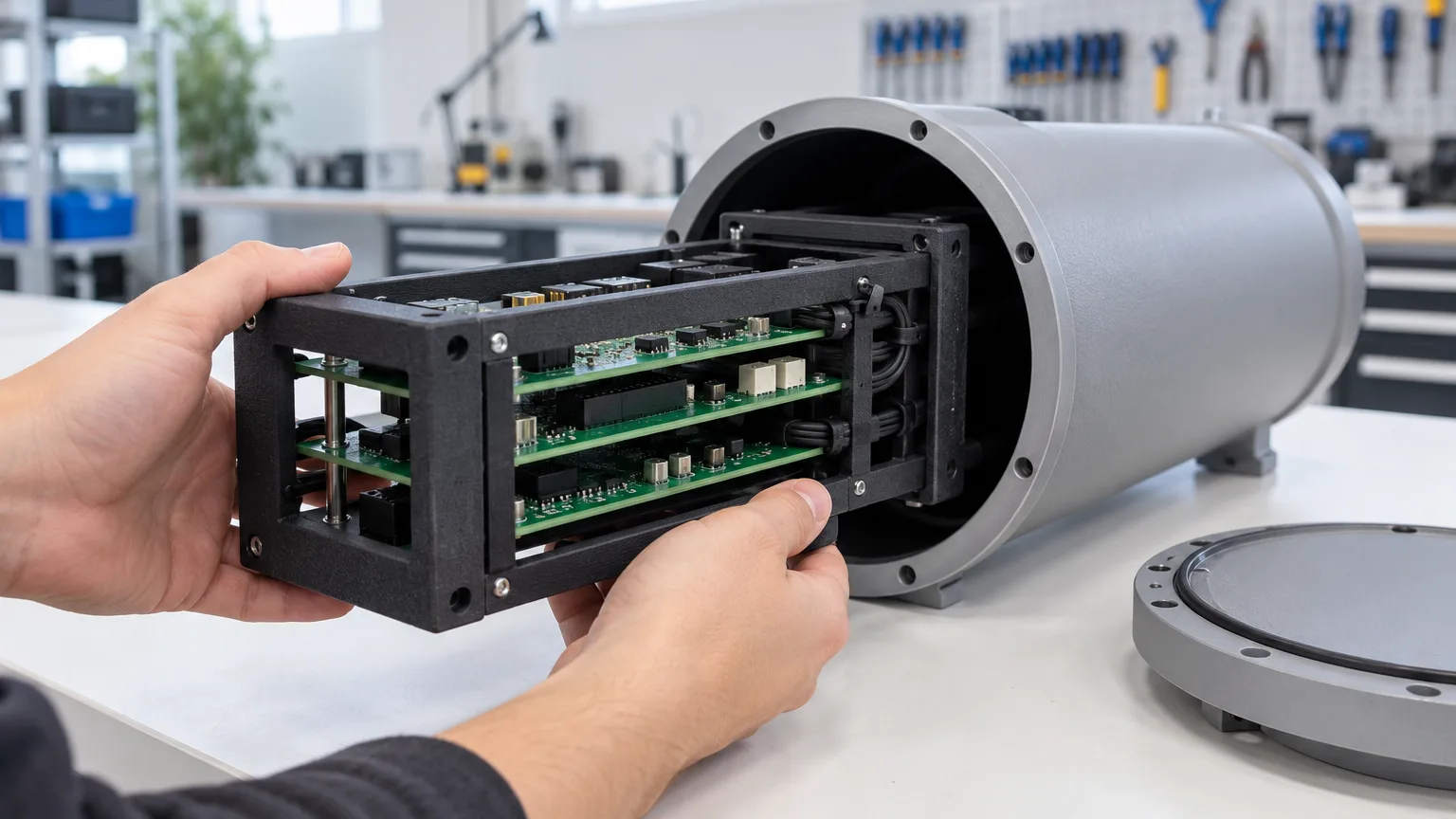
An electronics chassis needs to locate circuit cards, manage wiring and fit inside its housing. Forge Labs supplied these internal components in black SLS PA12 as repeat kits. Printed brackets, adjustable pads and cable supports combined detailed geometry with the ability to reorder small lots without tooling.
The useful decisions are in the interfaces: slotted pads allow adjustment at assembly, modelled part IDs distinguish similar brackets, and drawing notes identify the dimensions that matter. Those details are transferable to electronics kits beyond subsea hardware.
The Project at a Glance
- Application: electronics chassis parts for subsea pressure housings, ordered as a kit
- Parts: card-mounting brackets, adjustable slide pads, support rails and cable management
- Process: SLS, with parts sized to share compact builds
- Material and finish: Nylon PA12, dyed black in-house on DyeMansion equipment
- Orders: repeat kit orders from released files, with new components added as separate designs
- Delivery: reviewed kit lots shipped in 3 to 7 business days
What Goes Into an Electronics Chassis
The chassis is a frame that holds the vehicle's circuit cards in a stack and slides into the bore of the housing. The printed parts fall into four types.
Card-mounting brackets
The brackets combine mounting tabs, bolt holes and open sections that leave room around the electronics. Raised part IDs distinguish similar pieces without a separate marking operation.
Slide pads
The pads support the chassis as it slides into the housing. Their curved contact face follows the bore, while slotted, counterbored fixing holes allow the installed position to be adjusted.
Support rails and cable posts
Support rails locate the assembly, and posts with cable-tie slots keep wiring clear of the circuit cards. Those holes and slots print with the part rather than being cut afterwards.
Process ChoiceWhy SLS PA12 Suits a Chassis Kit
The drawing specifications named SLS PA12 and the finish. A kit with many small designs is expensive to tool individually; printing lets each design run from its own file and share a build. Detailed features form with the rest of the part:
| Feature | Where it appears | What SLS PA12 does with it |
|---|---|---|
| Stepped tabs, bosses with cross holes, cut-outs | Card-mounting brackets | Unsintered powder supports every overhang, so nothing needs support structures or draft |
| Raised part IDs | Card-mounting brackets | Printed with the part; our SLS design guide asks for raised and recessed detail at least 0.5 mm wide and deep |
| Curved contact face | Slide pads | The curve comes straight from the model, with no form cutter or holding fixture |
| Rows of cable-tie slots | Cable posts | Slots print open in the same pass, with no secondary cutting |
| Multiple designs in one material | The whole kit | Any design can share any build, and every part follows the same finishing route |
The material suits the job too. PA12 is an electrical insulator: our PA12 data lists a volume resistivity of 1013 to 1015 Ω·cm and a dielectric strength of 92 kV/mm, useful in a part whose job is to hold circuit cards. It is ductile rather than brittle, which suits tabs and bosses clamped under screws. And every part fits the 200 × 250 mm bed of a small-frame EOS P110, where builds are short.
DrawingsThree Notes That Make a Drawing Fit for Printing
The slide pad drawing provides a useful structure for defining a printed part: dimension the functional interfaces, then explain how the rest of the geometry is controlled. Its notes address three questions:
- The part is 3D printed. Everyone from quoting to assembly knows which rules apply.
- The STEP file governs anything not dimensioned. The model, not the sheet, carries the rest of the shape.
- Undimensioned surfaces carry a stated band of ±0.2 mm. One line replaces a page of tolerances.
The model defines the shape, the drawing defines what is critical, and the notes say how to treat everything else. A drawing requirement is not evidence that the finished part achieved it; tolerance acceptance and inspection still need to be agreed.
Compare the band with the process
Our published tolerance for SLS PA12 is ±0.3% with a ±0.3 mm minimum, about ±0.3 mm on parts this size, so the pad drawing's ±0.2 mm band is tighter. That is not a reason to drop the band; it is the reason to raise it at quote. Our SLS design guide says tighter tolerances may be possible after a manual quote review, approved case by case. The useful questions are which surfaces truly need the tighter band and how they will be checked. On this pad, the slotted holes move most of the fit from the print to assembly, as the next section shows.
Check the title block
Like most templates, the team's title block was written for machined parts, with tight decimal-place tolerances and a machined-surface finish note that a printed surface does not meet as built. Override such defaults in a note, or call out the few features that need machining-class tolerance so they can be quoted as a secondary operation.
Design for AssemblySlotted Holes Under Counterbores Take Up the Tolerance
The slide pads touch something we do not make: the housing bore. Two sources of variation meet at that face, the print and the housing itself, and the pad drawing handles both simply. Each pad's two holes are slotted, giving a millimetre or two of travel before the screws are tightened, comfortably more than the ±0.3 mm SLS band, and the counterbores keep the screw heads recessed. The slots let each pad's final position be set at assembly against the actual bore, not by the print alone.
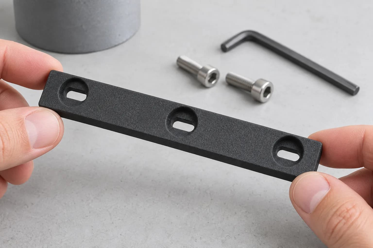
Slotted holes under counterbores let a printed part be set against its mating face at assembly instead of relying on the print alone.
Put the precision into the assembly, not the print. That applies wherever a printed part meets a bore, a rail or a mating part you do not control:
- Slot the holes in the direction that needs adjusting, and recess the fastener heads clear of the working face.
- Make the travel larger than the combined variation: the print band plus the mating part's own tolerance. PA12 is also hygroscopic (our PA12 data lists 1.5% water absorption in 24 hours); the dimensional effect is small, but it is one more reason not to depend on a line-to-line printed fit.
- Keep the tight band for the faces that set function, on a pad like this the curved contact face, not the whole part.
Model the ID In, and Say Which Face Prints Down
When several brackets in a stack are similar in size, fitting one in the wrong position is an easy mistake. The team modelled each bracket's ID into its top face as raised lettering before the first build, so every lot we have built carries them. A printed ID needs no label or marking step, and it cannot peel off.
The bracket drawings also say which face prints down: the face carrying the ID. That matches our SLS design guide, which recommends printing text and small details facing down in the build plane, because the quality of raised and recessed detail depends on orientation. The requirement was repeated in order and production notes. Put a requirement like this on the drawing, and send the drawing with every reorder, so it does not depend on someone remembering an order note.
There is a second reason to specify orientation. PA12 is not equally strong in every direction: EOS reports a tensile strength of 48 MPa and 18% elongation at break in X/Y for PA 2200, against 42 MPa and 4% in Z. When you choose the face that prints down, check where it puts the load path; a flat bracket laid on its face keeps its length in the build plane, where the material is most ductile. See our guide to part orientation.
ProductionHow a Mixed Kit Shares Production
The reviewed build records show a mixed kit running across compact SLS builds. All parts used the same material and finish, so different designs could share production without separate tooling.
Some builds carried mostly kit components; others shared space with unrelated work. Keeping the parts within a compact build envelope gave production flexibility to distribute the lot across machines.
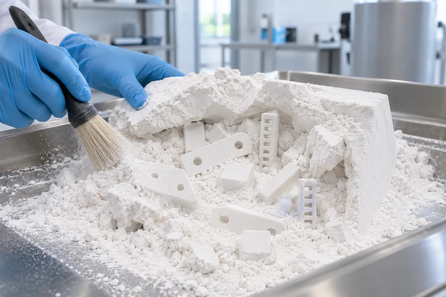
One material lets a mixed kit share builds; the parts come out white and are dyed black afterwards.
One larger kit shipped complete in five business days. Printing was only part of the route: cooling, depowdering, dyeing and packing also had to be scheduled. Planned print times alone do not establish the finished lead time.
Three things helped. Every part fits the small-frame bed, so the kit needed no large-frame slot. Every part is the same material, so any design could go into any build. And every part is the same colour, so the kit followed one finishing route. SLS PA12 prints white whatever colour is ordered, so mixed colours would not have split the builds, but they would have split finishing.
Revision ControlA Renamed File Is Not a Revision, but It Is a New File
Repeat orders reused the released component designs, with byte-identical files recorded for several parts. Retaining a controlled master file keeps a reorder tied to the version already reviewed and manufactured.
Some brackets were re-exported under descriptive filenames. A checksum could no longer tie them to the earlier file, so their geometry needed review. Volume, bounding box and rendered views are useful screening checks, but a feature-level comparison is needed to confirm that a different file contains the same design.
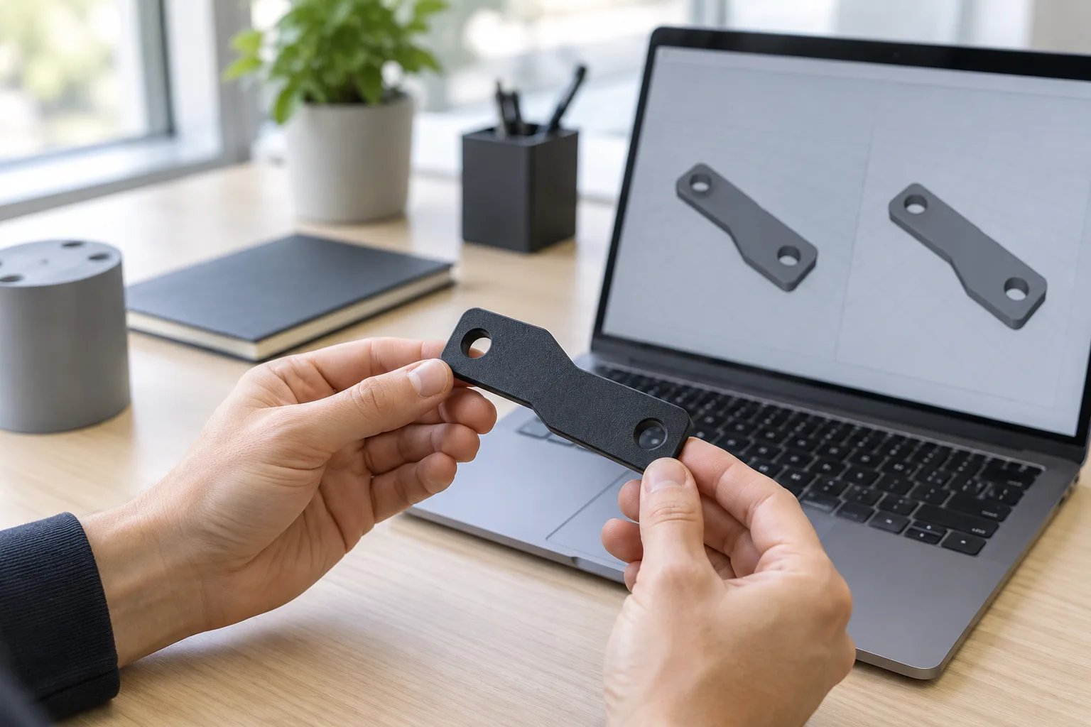
A new export needs a geometry check before it is treated as the same released part.
New components arrived as separate parts with their own files, while existing designs remained available for reorder. If a file is re-sent only to rename or re-export it, state that intent and verify the geometry; reserve revision identifiers for controlled changes.
FinishNo Paint Film Inside the Housing
The black on this kit, as on all our black SLS PA12 parts, is dyed in-house on DyeMansion equipment, not painted. Parts are cleaned of powder, bead-blasted to an even surface, then dyed in a heated, pressurised water bath where, as DyeMansion describes it, the dye reacts with the nylon rather than drying on top as a film. DyeMansion gives the penetration as up to about 0.2 mm, depending on the material.
On a chassis that matters in two places. A slide pad moves along the bore every time the chassis goes in or out, and a bracket tab is clamped under a screw head. A paint film would scuff or chip at both, and flakes do not belong inside a housing full of electronics. A dyed surface has no film to shed. It is still a surface colour, not a solid one: a slide face worn over many insertions can show lighter nylon, and DyeMansion's own testing found the choice of dye has no effect on scratch resistance. Measure fit-critical features after dyeing, not before. See our surface finishes for other options.
ResultsDelivery and Results
The reviewed kit lots shipped in 3 to 7 business days. Repeat components ran from released designs, while additional parts could be introduced without tooling changes. Shared material and finish kept the manufacturing route consistent across different component shapes.
LessonsWhat to Apply to Your Own Chassis and Kits
- Write the printed-part rules on the drawing. Say the part is printed, let the STEP file govern anything not dimensioned, and give undimensioned surfaces a band.
- Agree the band at quote. Our published SLS PA12 tolerance is ±0.3% with a ±0.3 mm minimum, so a tighter band, such as this pad's ±0.2 mm, should be agreed for the surfaces that matter, along with how they will be checked.
- Clear out machining defaults. Override title-block tolerances and finish notes written for machined parts, or call out the features that need machining as a secondary operation.
- Build adjustment into anything that touches a bore. Slotted holes under counterbores take up both the print band and the housing's own variation.
- Model part IDs in, and specify the face that prints down. Raised IDs at least 0.5 mm wide and high add almost nothing to the part, and a face-down callout helps keep them consistent from lot to lot. Check the load path when you choose that face.
- Say when a re-sent file is unchanged. A renamed export is not a revision, but it is a new file.
- Keep a kit in one material and one colour. A shared material lets different designs share builds; a shared colour keeps them on one finishing route.
Could Your Chassis Be Printed This Way?
Good candidates are the internal structure of enclosed electronics: card brackets, chassis frames, stops, slide pads, standoffs and cable management for robots, vehicles and instruments, ordered in tens or low hundreds of parts. They are small, detailed and numerous, and they change whenever the electronics do. In one material, they share builds and can be reordered in whatever mix the next build needs.
Check two things first. Electronics run warm in a closed housing: EOS reports a heat deflection temperature of 64 °C in X and 57 °C in Z at 1.8 MPa for PA 2200, so keep loaded brackets away from hot components or confirm their temperature. And if a part needs threads, heat-set inserts can be specified on SLS PA12; see the threads and inserts section of our SLS design guide. Dimensional inspection reports and a certificate of conformance are available on request.
See also repeat SLS PA12 production without tooling, drawing reconciliation for 3D printing, our robotics case studies on wearable robot actuator parts and an SLS PA12 sensor kit, and 3D printing for robotics.
Building Electronics Into a Pressure Housing?
Send us your chassis files, drawings and typical lot sizes. We will go through the drawing notes and tolerance bands with you at quote and set the kit up for repeat orders. We offer lead times from 2 business days, 24-hour turnaround on request, and next day shipping anywhere in the US and Canada.
Discuss Your Chassis With Us