

Small FDM parts can stay in production long after development ends. For robot-cell hardware, Forge Labs supplies ASA covers, Nylon 12 stops and carbon-fibre nylon flexures in repeat lots without tooling. The parts are ordered with released drawings that record material and print requirements, while critical bores have a separate sizing step.
Repeatability starts with a recorded print recipe: process, material, colour, layer height, shell and infill rules, and build orientation where it affects function. These parts show why small FDM bores need a sizing allowance, carbon-fibre filament needs a wear-resistant nozzle, and first-article checks belong in the production plan.
The Project at a Glance
- Application: equipment covers, mechanical stops and flexure springs for welding-automation robots, reordered as production parts
- Parts: small equipment covers, mechanical stops and carbon-fibre nylon flexures
- Process: FDM, 0.254 mm (0.010 in) layers on the cover and stop; on the spring, layer height chosen for dimensional accuracy
- Materials and finish: black ASA, black FDM Nylon 12 and black carbon-fibre nylon; the spring's bores are sized after printing
- Drawings: each drawing carries its print recipe; only the spring's bores and bosses are dimensioned as limits
- Orders: repeat lots of a few to a few dozen parts, with release dates and first-article requirements recorded on the order
- Delivery: lots are scheduled against the release dates on the purchase order
Three Small Parts, Three Materials
An equipment cover in ASA
The largest of the three is hand-sized: a folded, thin-walled cover for equipment on the robot system, with a round opening and a small fixing tab. A shape like this could otherwise be bent from sheet or moulded. For small repeat lots, printing avoids a dedicated forming setup or mould.
A mechanical stop in Nylon 12
The nylon stop includes a recessed fixing hole and undercut features. In a mould those undercuts would need side actions; in FDM they print in place, with support material under the overhangs. The drawing calls for FDM Nylon 12 in black, solid infill and an as-printed finish.
A flexure spring in carbon-fibre nylon
The flexure combines a thin spring section with mounting bosses and through-bores. Its critical bores and boss diameters are dimensioned as limits, with a stated minimum and maximum, rather than relying only on the title block's general tolerances. The drawing calls for carbon-fibre-reinforced nylon in black, with solid-fill shells and solid infill.
Process ChoiceWhy FDM Fits Small Repeat Lots
These are production parts, not prototypes, and FDM suits them for three reasons:
- No tooling and no minimum. Small lots are printed directly from the file, sized to the next release.
- Real thermoplastics. FDM extrudes the engineering material the drawing names: the cover is ASA and the stop is nylon, not a resin that imitates them.
- A recipe that can be written down. In SLS or MJF a part builds solid in a powder bed, with few settings to choose. In FDM, layer height, perimeters, infill and orientation are all choices, and each one changes the part. That is a risk if the choices are left open and an advantage if the drawing fixes them.
| Material | Used for | What it brings | What to plan for |
|---|---|---|---|
| ASA | Equipment cover | Stratasys rates it UV resistant: after 1,000 hours of accelerated UV weathering, stress at break went from 30.5 to 29.5 MPa. Stratasys lists a heat deflection temperature of 103 °C at 0.45 MPa. | Stratasys rates it limited against motor oil. Like all FDM parts, it is weakest across the layers. |
| FDM Nylon 12 | Mechanical stop | An unfilled nylon that Stratasys's compatibility table rates excellent against motor oil, petroleum greases and fuels. | Specify solid infill on a part that takes contact loads, as this drawing does. |
| Carbon-fibre nylon | Flexure spring | Stiff and light: carbon-fibre nylon is up to 60% lighter than aluminium. | The filament is abrasive, so it needs a hardened nozzle. Quoted on request rather than self-serve. |
ASA suits equipment covers in welding cells, where the arc gives off intense ultraviolet light. Stratasys describes it as similar to ABS but with better UV resistance, mechanical properties and aesthetics.
DrawingsThe Print Recipe Lives on the Drawing
An FDM supplier sets many variables before a part prints, and most of them change the part. Layer height affects surface finish and layer bonding. Shell count and infill set stiffness and weight. Orientation decides which loads cross the layer lines and which face comes out flattest. These drawings close those choices off in their notes:
| Recipe item | Equipment cover | Mount stop | Flexure spring |
|---|---|---|---|
| Process and material | FDM, ASA | FDM, Stratasys Nylon 12 | FDM, carbon-fibre-reinforced nylon |
| Colour | Black | Black | Black |
| Layer height | 0.254 mm | 0.254 mm | Chosen for dimensional accuracy |
| Shells | Not specified as a value | Standard solid-fill | Solid-fill |
| Infill | Not specified as a value | Solid | Solid |
| Face on the bed | Not called out | A datum face | The long edge |
| Limit dimensions | None | None | Bores and boss diameters |
Because the recipe is on the released drawing, any lot can be set up and checked against it. A reorder does not depend on anyone remembering how the last lot was made, on either side.
Write values, not "standard"
The stop and spring drawings call for solid infill. The cover drawing leaves shells and infill at the supplier's standard, so the supplier decides what standard means. Quoting systems and suppliers all have a default, and defaults differ: some print solid unless told otherwise, others fall back to a sparse fill. If the infill matters to stiffness, weight or how the part feels, write the value.
Name the face that prints on the bed
The stop's drawing names a datum face as the first layer, so the face the stop is located and measured from is formed flat on the build platform. A face parallel to the layers picks up no stair-stepping, so the surface every measurement starts from is one of the flattest on the part.
The spring's drawing puts its long edge on the bed, so the leaf stands on edge. Every layer then contains the whole wave profile, drawn as continuous perimeters, and when the spring flexes the bending runs along the extruded roads rather than across the layer bonds. That matters because FDM parts are much weaker across their layers. Stratasys's data for ASA, the cover material, shows the gap: 5.9% elongation at break printed on edge (XZ, the spring's orientation) against 1.8% printed upright (ZX), and notched impact strength of 43.1 J/m against 23.8 J/m.
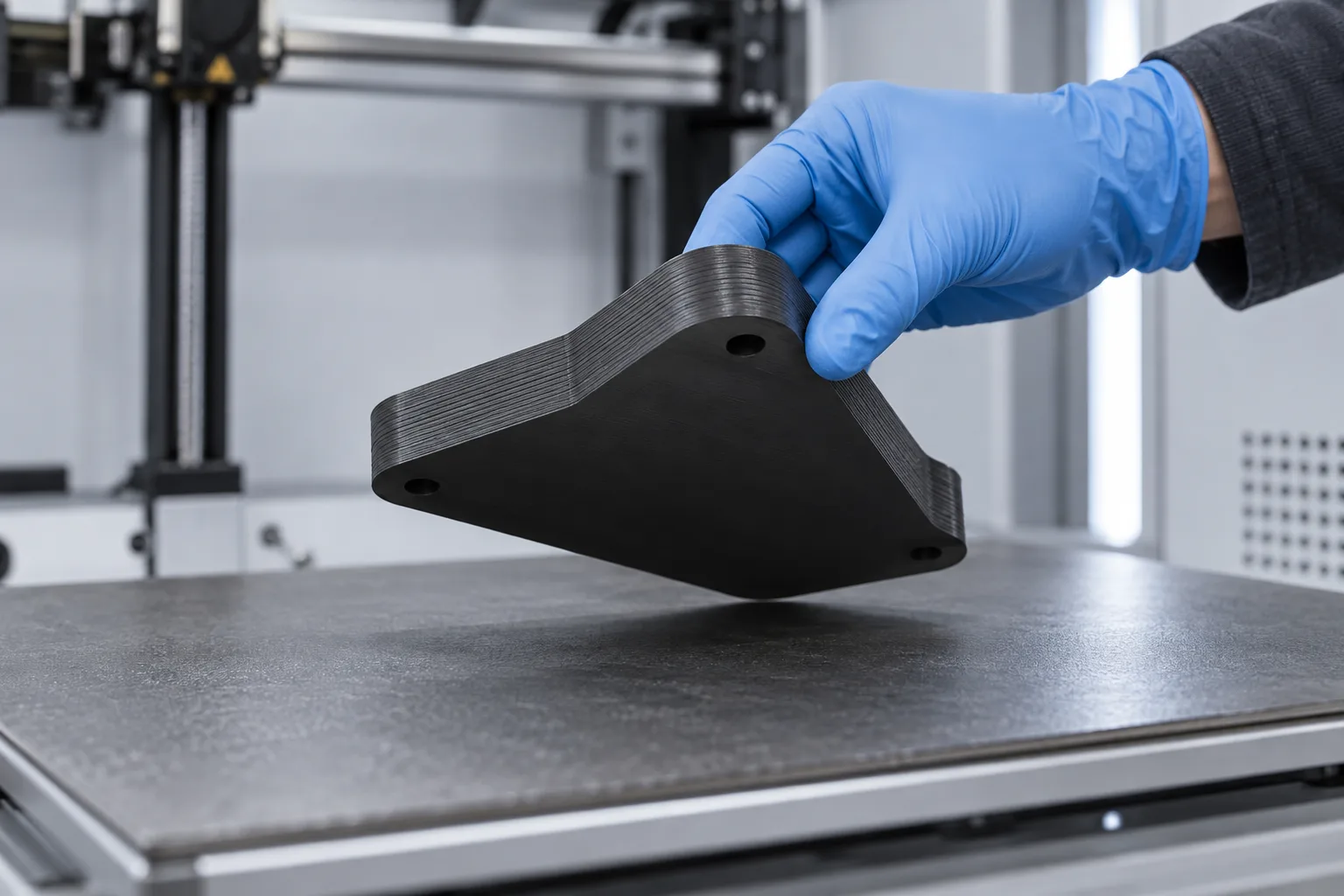
The face that prints on the bed is built flat, parallel to the layers, which is why a drawing that names a datum face as the first layer protects that face.
The cover's drawing does not name a bed face, so the options were laid out when the part was first quoted. On a part like this, one orientation leaves less stair-stepping on the body of the part and more on the round opening, and the other the reverse, with different support use and a different price. If your drawing leaves orientation open, ask for the options, then put the choice on the drawing. See our guide to part orientation.
HolesSmall Vertical Bores Print Undersize
With the spring standing on edge, the bores through its end bosses run vertically, perpendicular to the build sheet. A vertical hole in FDM is built as a stack of small rings of extruded road. The toolpath approximates the circle, the road spreads as it is pressed down, and the plastic contracts towards the hole as it cools. Small holes therefore come out undersize. The first few layers are also squashed slightly wider against the bed, leaving a lip known as elephant's foot along the bottom edge and at the bed end of each bore.
Our FDM design guide notes that, depending on orientation, round holes can come out oval, and that vertical holes print more accurately than horizontal ones. A vertical hole still closes up as it cools, and the guide recommends printing a hole smaller and drilling it out when accuracy matters. The spring's bores follow the same principle: they print undersize, and the order notes call for them to be reamed and for the elephant's foot to be cleared from the first-layer edge. The production instructions also call for a first article to check hole shrinkage before the full lot, and identify reaming as a separate operation.
Dimensions apply after finish
These drawings state that dimensions apply after finish. For the spring, that means the bore limits apply after the bores are sized, not to the hole as printed. The sizing step is therefore part of the specification, not a repair.
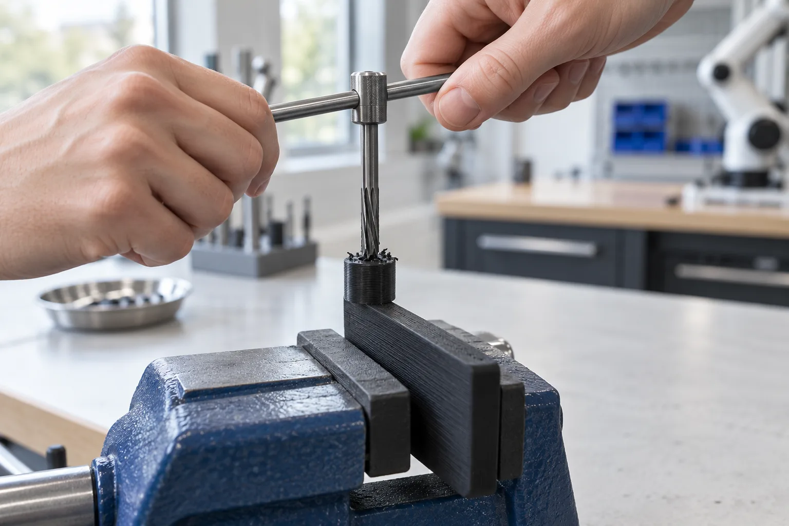
Small vertical holes print undersize in FDM, so critical bores are dimensioned as limits and sized after printing.
For your own parts:
- Dimension critical bores as limits. A minimum and maximum tells the supplier which holes need sizing and what the target is.
- Print the hole under the lower limit. A reamer needs material to cut; a hole printed at nominal can end up partly sized and partly as printed.
- Leave wall around the bore, so the boss can be reamed without splitting along a layer line.
- Put the sizing step on the PO, with its target, so it is planned for every lot rather than discovered at inspection.
Carbon-Fibre Filament Needs a Hardened Nozzle
Chopped carbon fibre makes nylon stiff and light, but it is abrasive. A standard brass nozzle wears as fibre-filled filament runs through it, the orifice grows, and the width of every extruded road changes with it. On a small part with limit-dimensioned bores, that drift shows up as dimensional change from lot to lot. The spring's order names the nozzle to use, so it belongs in the recipe alongside the material. For carbon-fibre filament, that means a hardened nozzle.
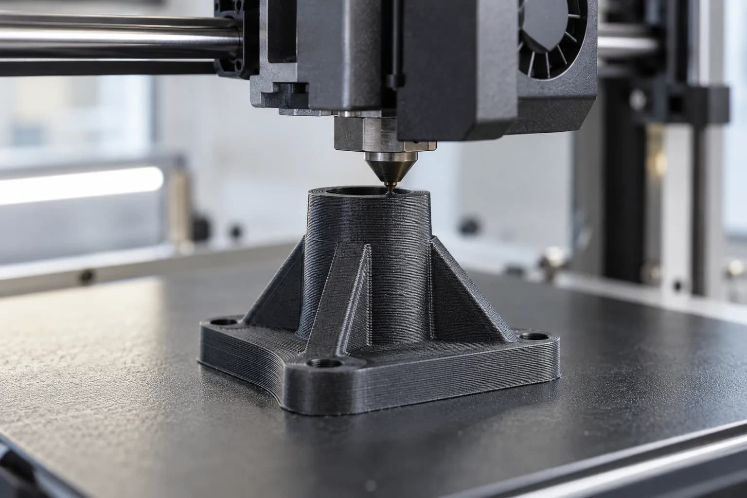
Chopped carbon fibre is abrasive, so carbon-fibre nylon runs through a hardened nozzle that resists wear.
Orientation matters even more in a fibre-filled material. The fibres tend to line up along the extruded roads, so the material behaves like a composite laminate: stiffest along the roads and weakest across the layers. That makes the spring's on-edge orientation more important still.
ProductionHow Each Reorder Runs Through the Shop
Copy the recipe onto every order line
An order line holds a configuration: process, material, colour, layer height and infill. Copying the drawing's recipe into it, line by line, keeps a lot from falling back to a quoting default. Production notes carry what a configuration cannot hold, such as the first-article requirement, the nozzle and the sizing step. Reorders can be placed from order history, which carries the previous lot's configuration forward; check it against the drawing before the lot is released.
Same file, checked by geometry
The reviewed repeat files had matching volumes, while some exported bounding boxes differed. Export orientation can change an overall size comparison without changing the design. Use file identity and a geometry comparison to confirm an unchanged part; volume, surface area and bounding box are useful screening checks, but matching numbers alone do not prove two shapes are identical.
Scale set per material, proven on a first article
FDM parts shrink as the extruded plastic cools, and each material shrinks by its own amount, differently in the build plane than across the layers. Scale corrections are therefore set per material, and where an order calls for a first article, it confirms them before the lot runs. On a part longer than about 100 mm, a scale error of a fraction of a percent can use up much of a general tolerance band such as our FDM tolerance of ±0.25 mm or ±0.3%, whichever is greater.
A single small FDM part can print in hours, allowing it to be measured before the lot is committed. Record the required checks on the order, including the condition in which a dimension is measured: as printed, after support removal or after bore sizing.
SchedulingDated Releases on One Purchase Order
Scheduled releases let the same design run in smaller lots as it is needed. In these orders, the purchase order records the release dates, giving production time to plan first articles and bore sizing. Order-to-ship duration then reflects the requested schedule as well as manufacturing time; it should not be read as a measure of printer speed.
Dated releases suit both sides. The supplier can plan builds, first articles and sizing steps around known dates, and the builder does not need to stock parts ahead of each release. One detail is worth fixing on the PO itself: write release dates in ISO format (YYYY-MM-DD). Month-first and day-first conventions both appear on purchase orders and in order systems, and a date such as 03/04 means a different month to each.
ResultsDelivery and Results
- Production without tooling: released designs reordered in small lots from repeat files.
- A steady cadence: purchase orders set the delivery cadence before production.
- Control written into the order: a sizing step and a specified nozzle on the flexure, with first-article requirements recorded for repeat production.
What to Apply to Your Own FDM Production Parts
Key Takeaways
- Put the print recipe on the drawing. Process, material grade, colour, layer height, shells, infill and the face on the bed. Copy it into every order so nothing falls back to a default.
- Write values, not "standard". A quoting system's default infill may not be what you mean.
- Name the first-layer face. Put datums and flat faces on the bed, and orient flexing parts so bending runs along the layers. If orientation is open, ask for the options, then record the choice.
- Dimension critical bores as limits and plan a sizing step. Small vertical holes print undersize. Print them under the lower limit, ream to the band, and remember that dimensions apply after finish.
- Use a hardened nozzle for carbon-fibre filament, and say so on the order, so the road width stays the same from lot to lot.
- Prove scale on a first article, then run the lot. Shrink differs by material and axis, and a first article of a small FDM part prints in hours.
- Confirm revisions with a geometry comparison. Volume and surface area help screen files; a bounding box can shift with export orientation.
- Use dated releases on one PO, and write the dates in ISO format.
Could Your Robot Cell Parts Be Made This Way?
Good candidates are covers, guards, stops, brackets, cable guides and small flexures for robot cells and automation equipment: released designs ordered in lots of a few to a few dozen, where tooling is hard to justify. FDM suits parts that need a real thermoplastic and can show layer lines. ASA and FDM Nylon 12 both accept heat-set inserts (see the threads and inserts section of our FDM design guide), and carbon-fibre nylon is quoted on request. Where a bore needs more than reaming, machining can be quoted as a secondary operation.
If a part needs finer detail or a more uniform surface than FDM's layer lines allow, compare SLS PA12. First article inspection or production sampling can be added when the drawing or order calls for it, and dimensional inspection reports and a certificate of conformance are available on request.
For more robotics work, see our case studies on ISE's FDM ASA underwater vehicle mounts, humanoid robot hand parts and an SLS PA12 subsea electronics chassis, and our 3D printing for robotics page. For more on FDM settings, see FDM infill and drawing reconciliation for 3D printing.
Reordering Small Parts for Robot Cells?
Send us the drawing with its print recipe, or ask us to propose one, along with your typical lot size and release dates. We will set the part up for repeat lots. We offer lead times from 2 business days, 24-hour turnaround on request, and next day shipping anywhere in the US and Canada.
Discuss Your Parts With Us