Fused Deposition Modeling3D Printing Design Guidelines
Our design guidelines for Fused Deposition Modeling (FDM) include important information to improve part quality, minimize costs, and reduce overall manufacturing time. By following the guidelines, you can produce high-quality parts, reduce expenses, and improve productivity.
Quick Specifications

Quick Navigation
Overview
Fused Deposition Modeling (FDM) melts thermoplastic filament and extrudes it layer-by-layer through a heated nozzle onto a build platform. This versatile technology excels at producing large-scale prototypes and functional parts with exceptional material variety and cost-effectiveness.
These FDM design guidelines cover essential considerations for wall thickness, layer adhesion, support structures, and material behavior. Following these best practices ensures your parts achieve optimal strength, dimensional accuracy, and surface quality while minimizing print time and material costs.

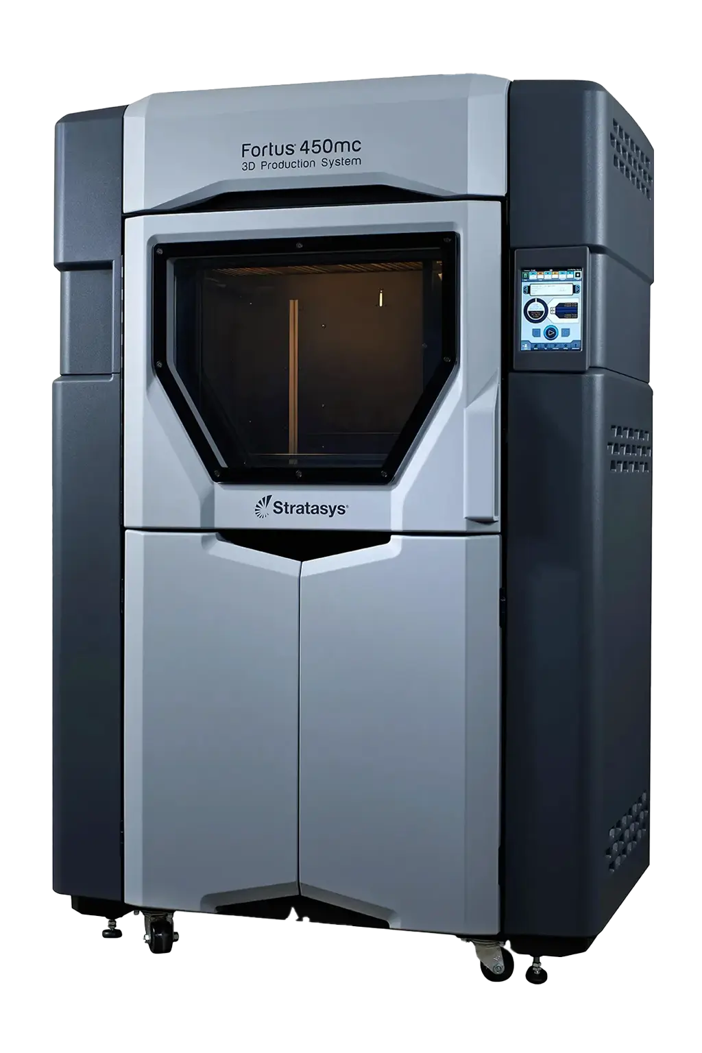
Maximum Build Volume
914mm x 609mm x 914mm (36" x 24" x 36")
FDM produces parts up to 36 inches in a single build. Parts larger than the build volume can be printed in sections and assembled.
This is one of the largest build volumes available for industrial FDM systems.

Tolerances
Machine-dependent tolerances
Fortus 450 (16" x 14" x 16"): ±0.25 mm (±0.010"), or ±0.2%, whichever is greater. Fortus 900 (36" x 24" x 36"): ±0.762 mm (±0.030"), or ±0.5%, whichever is greater.
Tolerances as tight as +/- 0.127 mm (+/-0.005") can be achieved on request with engineering drawings.

Layer Height
127 - 330 microns
Standard layer height is 254 microns (0.010″) unless otherwise stated. Industrial FDM machines can print parts with custom layer thickness, in the range of 127 - 330 microns thick. Thicker layers typically result in better adhesion and better mechanical properties.
Thicker layers provide better strength but lower surface quality.

Surface Finish
Visible Layer Lines
Parts made with FDM will always show visible layer lines, especially on curved surfaces. However, the visibility of layer lines can be reduced with smaller layer heights at the expense of print speed.
Layer lines are inherent to the FDM process and cannot be completely eliminated.
Wall Thickness
Thicker geometries and walls with variable thickness are at risk of deformation due to shrinkage and stress. In general, follow wall design rules for injection molding to achieve a more uniform and consistent part.

Minimum Wall Thickness
1mm (0.039")
Supported walls are connected to two or more sides and are thick enough to support the model.
Recommendations:
- Thicker walls provide better strength and stability
- Consider nozzle diameter when designing wall thickness
- Multiple wall perimeters improve part strength

Minimum Unsupported Wall Thickness
1mm (0.118")
Unsupported walls are connected on only one side or edge.
Unsupported walls may sag or curl during printing, especially with larger layer heights.

Minimum Pin Diameter
3mm (0.197")
The minimum pin size depends on a combination of parameters such as; part orientation, nozzle diameter, and length of the pin.
Recommendations:
- Larger diameters required due to FDM layer adhesion characteristics
- Consider pin length and support requirements
- Test critical pin features for strength requirements
Minimum Detail Size
The quality of engraved and embossed features depends heavily on part orientation and the resulting thermal effects of printing. Forge Labs recommends using a 3-5 degree draft angle when extruding text as the extra taper from the draft can help preserve intricate details.

Debossed Details
Minimum Width: 1mm, Depth: 0.3mm
Debossed details are recessed features on your model. Making these too small can result in closed gaps and loss of detail.
Add draft angles to debossed features for better definition and easier support removal.

Embossed Details
Minimum Width: 1mm, Depth: 0.5mm
Embossed details are raised features on your model. These usually resolve better than engraved details. Extruded text should have a wall thickness of at least 1.5mm (0.059") when printed flat, and 2mm (0.079") when printed vertically.
Recommendations:
- Orient embossed features to minimize support requirements
- Use adequate thickness for layer adhesion
- Consider nozzle diameter limitations

Text
Minimum point size: 16pt
Minimum suggested text size on the top or bottom build plane of a FDM model is 16 point boldface. Minimum suggested text size on vertical walls is 10 point bold.
Recommendations:
- Use bold, sans-serif fonts for best results
- Orient text horizontally when possible
- Consider support elimination for vertical text
Part Clearances
The mechanical performance of printed assemblies is sensitive to variables such as print orientation, layer height and machine tolerances. It is best to test and refine any mated parts before committing to a full production run.

Minimum Clearance
0.5mm (0.019")
Clearance is the distance between two moving parts on hinges, joints, mating parts, etc.
Insufficient clearance can cause parts to fuse together during the printing process.

Minimum Press Fit
0.1mm (0.004")
For a tight press fit, add a small offset, and chamfer the leading edge to ease entry. Always print an initial test part to dial in dimensions.
Recommendations:
- Test press fits extensively before production
- Account for material thermal expansion
- Consider surface finish effects on fit

Hinges
Minimum: 0.6 mm (0.023")
This defines the minimum allowed gap between a bush and a bolt, to avoid bonding of the hinge parts.
FDM can print functional assemblies, but larger clearances may be needed compared to powder-based processes.
Holes & Gaps
Hole accuracy can vary depending on print orientation, thickness of surrounding material and support structures. For tight tolerances, consider printing center marks and post-machining them instead.

Minimum Hole Size
0.5mm (0.019")
Depending on orientation, circular holes can resolve as ovals – if higher accuracy is required, printing the hole smaller and then drilling it out is recommended.
Vertical holes print more accurately than horizontal ones due to layer stacking.

Minimum Gap Size
0.5mm (0.019")
Gaps or slots can fuse if made too narrow, and support material may be difficult to remove. If possible, orient gaps along the xy-plane for highest accuracy.
Recommendations:
- Orient gaps horizontally for best accuracy
- Consider support removal accessibility
- Account for material thermal expansion

Minimum Drain Hole Size
4 mm (0.15")
Hollow features may be filled with soluble support material, and must be designed with drain holes so that the support can be dissolved and removed during cleaning. Larger parts or parts with complex internal features may require larger holes to allow support material to fully dissolve.
Soluble supports make complex internal geometries possible with proper drain hole design.
Part Geometry
Part geometry can be optimized for 3D printing to reduce material usage, increase strength and rigidity, and take advantage of machine capabilities.

Fillets
Design Recommendations
Fillets can be used to reduce stress concentrations and increase the strength of your part. When designing fillet features across inside and outside corners, it is best to have them share a common center point in order to maintain a consistent wall thickness.
Recommendations:
- Use fillets to improve layer adhesion at corners
- Consider printing orientation when sizing fillets
- Larger fillets may improve part strength

Bosses and Ribs
Design Recommendations
Bosses and ribs are an effective way to add strength and stiffness to a part while keeping material consumption to a minimum, this can also reduce build time and use less support material.
Recommendations:
- Bosses and ribs can generally be matched to part thickness
- Use ribs to support large flat surfaces
- Consider heat set insert compatibility for bosses

Support Structures
FDM Printing
A separate support material is used to hold the part up during building. All materials aside from ULTEM use soluble support material that is dissolved, leaving no imperfections on the surface of the part. Support for ULTEM has to be manually removed and can leave some minor scratches on parts.
Soluble supports enable complex geometries with excellent surface finish on supported surfaces.

Infills
FDM Printing
Infills are used in FDM printing to save material and print time while maintaining the overall mechanical properties of the part. Parts will be printed solid unless otherwise specified. 'Sparse fill' prints large volumes with a honeycomb structure instead of solid plastic.
Hollow walls require drain holes for support material removal and must be designed accordingly.
Threads & Inserts
FDM is not well suited for printing threads, so inserts are recommended. As a general rule, avoid printing hardware.

3D Printed Threads
FDM Guidelines
Very large threads can be printed, but most threads do not perform well in FDM. The use of inserts is recommended.
Printed threads in FDM are generally weak and not suitable for repeated use.

Tapping & Threading
FDM Post-Processing
Design parts with holes sized for tapping, or center marks for drilling a pre-tapped hole. Tapping removes material, puts pressure on the surrounding geometry, and fastener locations are often points of stress, so make sure there is enough material surrounding the tapped hole.
Tapping FDM parts often produces weaker threads that are not suitable for frequent re-use.

Heat Set Inserts
FDM Applications
Threaded inserts can be glued in, or heated and pressed in. Heat set inserts require a soldering iron with an installation tip, which softens the plastic walls, allowing the insert to be pushed into the hole or boss before the plastic hardens around the insert.
Recommendations:
- Design boss diameter to match insert specifications
- Add chamfer or fillet around boss edge
- Account for thermal shrinkage in hole sizing
Post Processing
While printed parts are highly functional and accurate, there are a variety of ways to modify them after printing to enhance durability or aesthetics.

Sectioning, Joining, and Bonding
FDM Post-Processing
Parts too big to fit on the print tray can be split in CAD and printed in multiple parts, then glued or press fit. Use joinery features, such as tongue and groove, to ensure the sections are aligned and bond tightly.
Recommendations:
- Test joint strength with prototype assemblies
- Consider layer direction effects on bond strength
- Use appropriate adhesives for the material

Post-Machining
FDM Machining
Parts can be machined to tighter tolerances using traditional or CNC subtractive manufacturing equipment.
Sharp tools and proper speeds/feeds are important when machining FDM parts.

Coatings
FDM Finishing
Parts can be sanded, primed, and painted for an excellent surface finish. Parts can also be coated with a lacquer, varnish or clear coat for various custom finishes.
Recommendations:
- Sand layer lines before painting for smooth finish
- Use appropriate primers for plastic substrates
- Consider UV resistance for outdoor applications

Vapor Smoothing
FDM Post-Processing
Vapor smoothing uses acetone vapor to increase plasticity of the material allowing it to flow, smoothing layer lines. With enough exposure, the resulting finish can be uniform and glossy, although this comes at the expense of dimensional accuracy. This is only applicable to ABS and ASA materials.
Vapor smoothing reduces dimensional accuracy and is only compatible with certain materials.
Ready to Start Your Fused Deposition Modeling Project?
Upload your design and get an instant quote optimized for fused deposition modeling manufacturing.
Click to start your quote
STL, STEP, OBJ, 3MF supported • Get instant pricing