
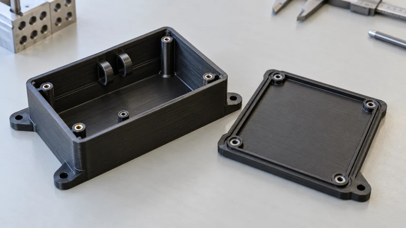
An aircraft electronics enclosure needs to protect its components, hold its mounting points in position and leave room for the wiring that connects everything together. Forge Labs manufactured black ULTEM 9085 enclosure samples for an aircraft systems application, working through the small features that determine whether a housing is practical to print, finish and assemble.
The useful engineering work centred on the mounting face, the print direction and the internal cable guides. Those details connected the drawing to the shop floor: where the layers ran, where support material was needed, how it could be removed and what needed checking before the parts left for evaluation.
The Project at a Glance
- Part: a compact electronics enclosure with mounting holes and integrated cable-retaining features
- Process: Fused Deposition Modeling (FDM), using solid-filled black ULTEM 9085
- Engineering focus: drawing-defined build orientation, small internal features, support removal and dimensional inspection
- Turnaround: samples shipped in about two and a half working weeks, including process trials and finishing
- Result: completed enclosure samples, a workable approach to the cable guides and positive customer feedback on sample quality
A Lightweight Housing With the Features Built In
A housing can do more than surround a circuit board. Its walls protect the electronics, its mounting features locate the assembly and its internal guides keep cables away from neighbouring components. Printing these features together gives the designer freedom to place them where the assembly needs them. A cable route can follow the available space, and a fixing point can sit close to the component it supports.
That makes FDM useful while an enclosure is being refined for production. Changes to a wall, mounting feature or cable guide can go into the CAD model and the next build, with no mould to modify. The same process can make evaluation samples and subsequent small batches, allowing the design team to work with the intended engineering material early.
ULTEM 9085 combines heat resistance, low weight and stiffness in a thermoplastic suited to functional housings. For an enclosure, that combination helps maintain the shape of walls and fixing points while keeping the assembly light. Its electrical insulation is useful around electronics, and its toughness supports the handling involved in installation and servicing.
Fire performance also drove the material choice in this application. ULTEM 9085 has published flame, smoke and toxicity test data for defined filament and print configurations. Matching the grade, colour, build setup and documentation to the part's requirements gives an aircraft design team a useful starting point for qualification. Those choices belong alongside the geometry from the beginning.
Drawing to BuildMake the Mounting Face the Reference
The supplied drawing specified FDM, black ULTEM 9085 and a build direction relative to a datum face. A datum is the surface or feature used as the reference for other dimensions. Here, the relationship between that face and the build plane made print orientation part of the manufacturing definition.
This matters because an FDM part is built from deposited roads of plastic. Loads carried along those roads and loads pulling layers apart act differently on the part. For a housing, orientation also changes how the mounting holes resolve, how the rim is formed and which internal features need support. The best setup brings those requirements together.
We reviewed the orientation with the designer before printing. The aim was good definition across the main enclosure features, followed by focused work on the smaller internal details. Fixing the orientation early also gave the dimensional checks a consistent reference as the print settings were refined.
Our FDM design guide gives a general tolerance of ±0.3%, with a ±0.25 mm minimum. On a compact housing, tenths of a millimetre can determine whether fasteners pass freely through a hole or a neighbouring part clears the wall. A drawing becomes most useful when it identifies the mounting face, hole positions and clearances that control assembly. Those are the features worth concentrating inspection effort on.
Cable Guides Need Room to Print and Finish
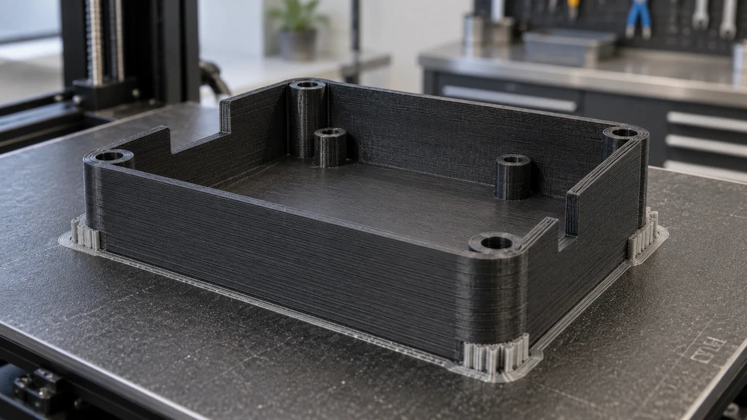
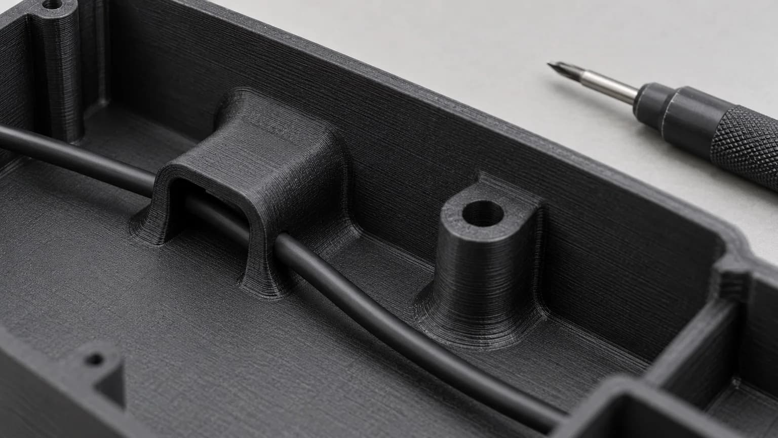
The internal cable guides were small, but they needed particular attention. Their job was straightforward: keep a cable supported inside the enclosure. Their shape also created short overhangs where the printer had to deposit hot material above an open gap.
ULTEM uses breakaway support that is removed by hand. Access therefore matters as much as the ability to print the feature. A narrow opening may accommodate the cable perfectly while leaving little room to remove support cleanly. On a small guide, tool access and the strength of its attachment to the wall deserve attention together.
We tested the features in ULTEM, examined the support behaviour and refined the printing approach. The designer confirmed there was room to adjust the guides while preserving their cable-support function. That gave the manufacturing review a useful target: maintain the cable route and clearance, with enough freedom to improve how the feature was made.
For a similar design, a rounded connection to the housing spreads bending loads at the guide's root. A more open shape can improve access for finishing, and a shorter unsupported span can make deposition easier to control. These are small geometric decisions with a practical payoff: stronger handling points, simpler cleaning and less time spent working inside the finished enclosure.
Refine the Print, Then Check the Finished Part
The order called for solid-filled black ULTEM 9085. Our review covered the drawing, the mating features and the intended orientation before internal print trials. The trials let us examine the walls, corners and cable guides in the material that would be supplied.
Industrial FDM uses a controlled heated chamber to help the deposited layers bond and limit distortion as the part builds. On an enclosure, this supports consistent walls and mounting surfaces. Toolpath planning then determines how the plastic roads meet around holes, corners and narrow features. Reviewing those transitions is useful wherever a hole interrupts a thin wall or a small guide grows out of a larger surface.
The early prints gave us a sound main enclosure to work from. Further trials concentrated on the internal guides and toolpath details, and we established a workable way to produce the guides before the samples moved to quality control. Finishing and inspection followed printing, with particular attention to the areas that needed support removal.
The samples shipped about two and a half working weeks after the order was placed. That interval included engineering trials, feature refinement, finishing and preparation for evaluation. The value of additive manufacturing was the ability to work through those decisions on real parts, without waiting for a production mould or committing the design to tooling.
Inspection and RepeatabilityUse the First Parts to Establish What Good Looks Like
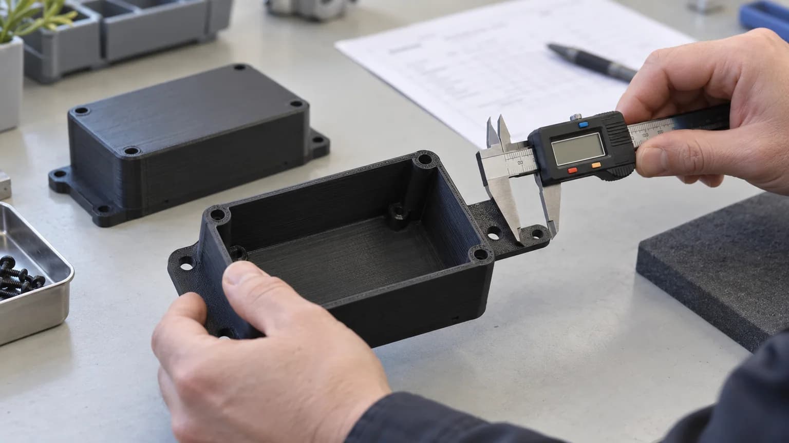
First article inspection was part of the planned sample work. For a housing like this, dimensional checks help establish whether the mounting features and clearances match the drawing before the part reaches the assembly bench. The customer can then evaluate cable routing, access and fit with the surrounding hardware using the finished samples.
You can include first article inspection when configuring parts in our portal. Its value is concentrated attention on the features that matter to your assembly, giving you more confidence before ordering additional parts. A clear mounting reference and a small set of meaningful acceptance dimensions make that inspection especially useful.
Repeatability also depends on retaining the manufacturing setup used for the samples. In this work, the customer asked for the orientation and print settings to be recorded for future manufacture. Material identity, layer height, toolpaths and finishing approach all contribute to reproducing a part. Keeping that information with the drawing and CAD revision makes the next order easier to compare with the samples already evaluated.
A Practical Route From Enclosure Design to Manufactured Samples
Forge delivered the enclosure samples, and the customer's follow-up confirmed good sample quality. The work established a useful manufacturing approach around the existing part: a defined orientation, attention to the small cable features and an inspection plan tied to the drawing.
The lesson applies to control housings, sensor enclosures and other small aerospace components. Additive manufacturing brings the mounting and routing features into one part while keeping design changes accessible. The strongest results come from designing those features together with the build direction, finishing access and checks that will make the housing ready to assemble.
Developing an Aerospace Enclosure?
Share your CAD model, drawing and assembly requirements. We can review material options, build orientation and inspection needs, then manufacture samples for fit and functional evaluation.
Discuss Your Enclosure