Step 1 of 4
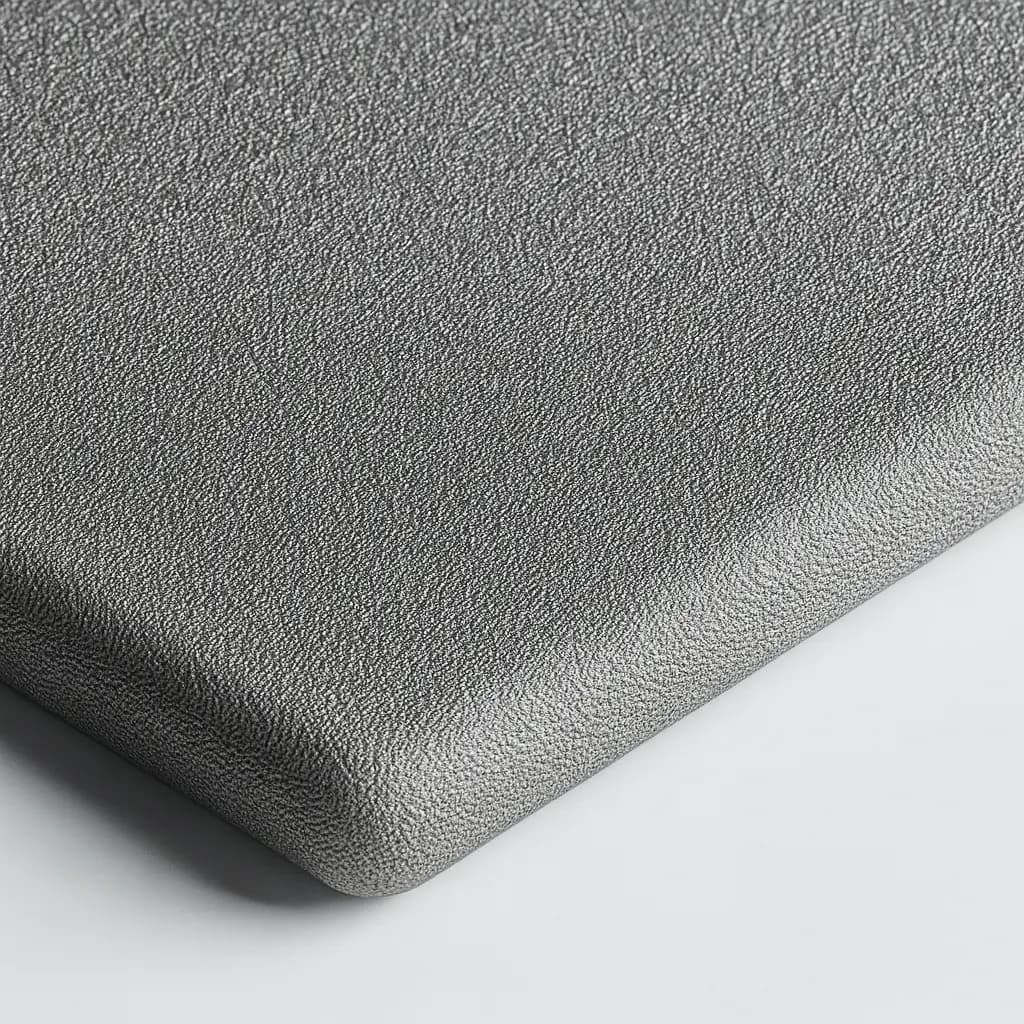
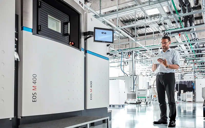
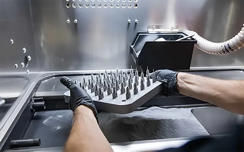
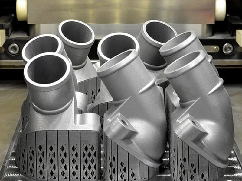
Powder Preparation
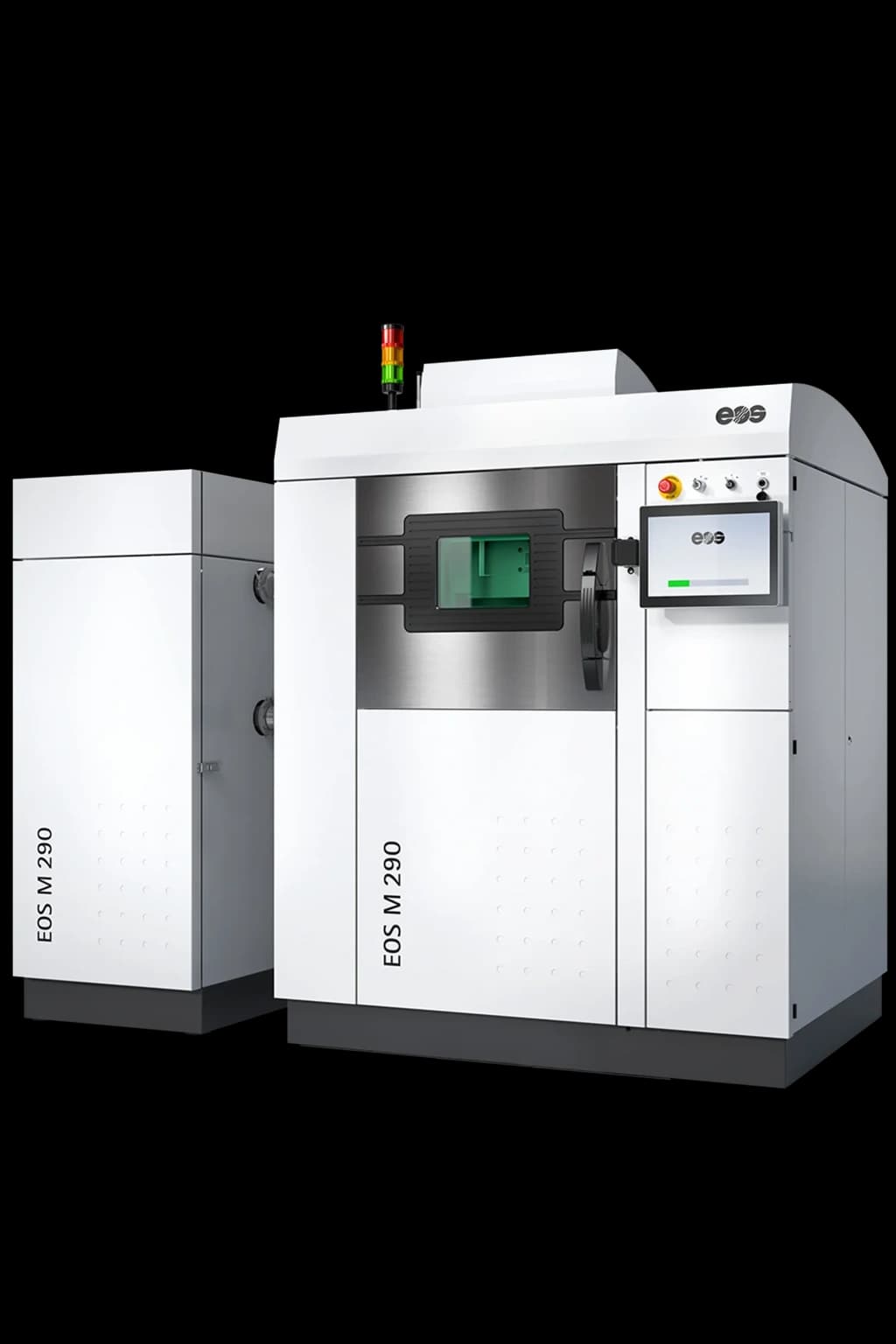
Fine metal powder is prepared and loaded into the machine. The build platform is preheated to optimal temperature to reduce thermal stress and improve part quality.
- Powder Size
- 15-45 microns
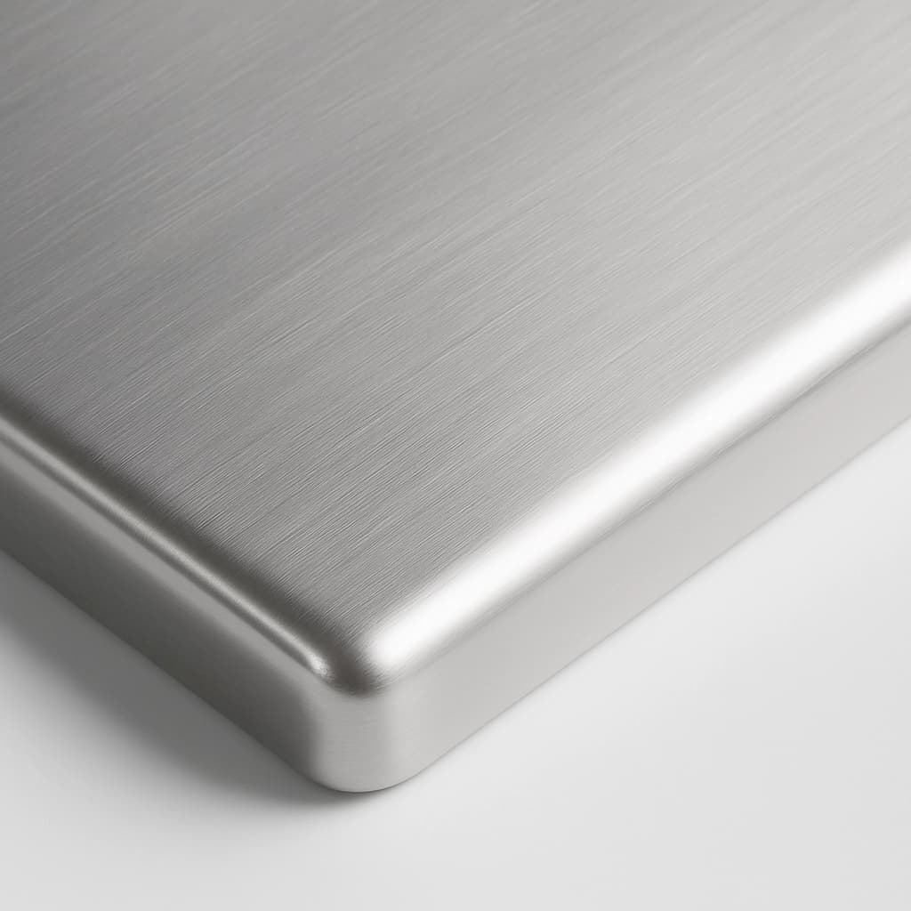
- Preheat Temp
- 80-200°C
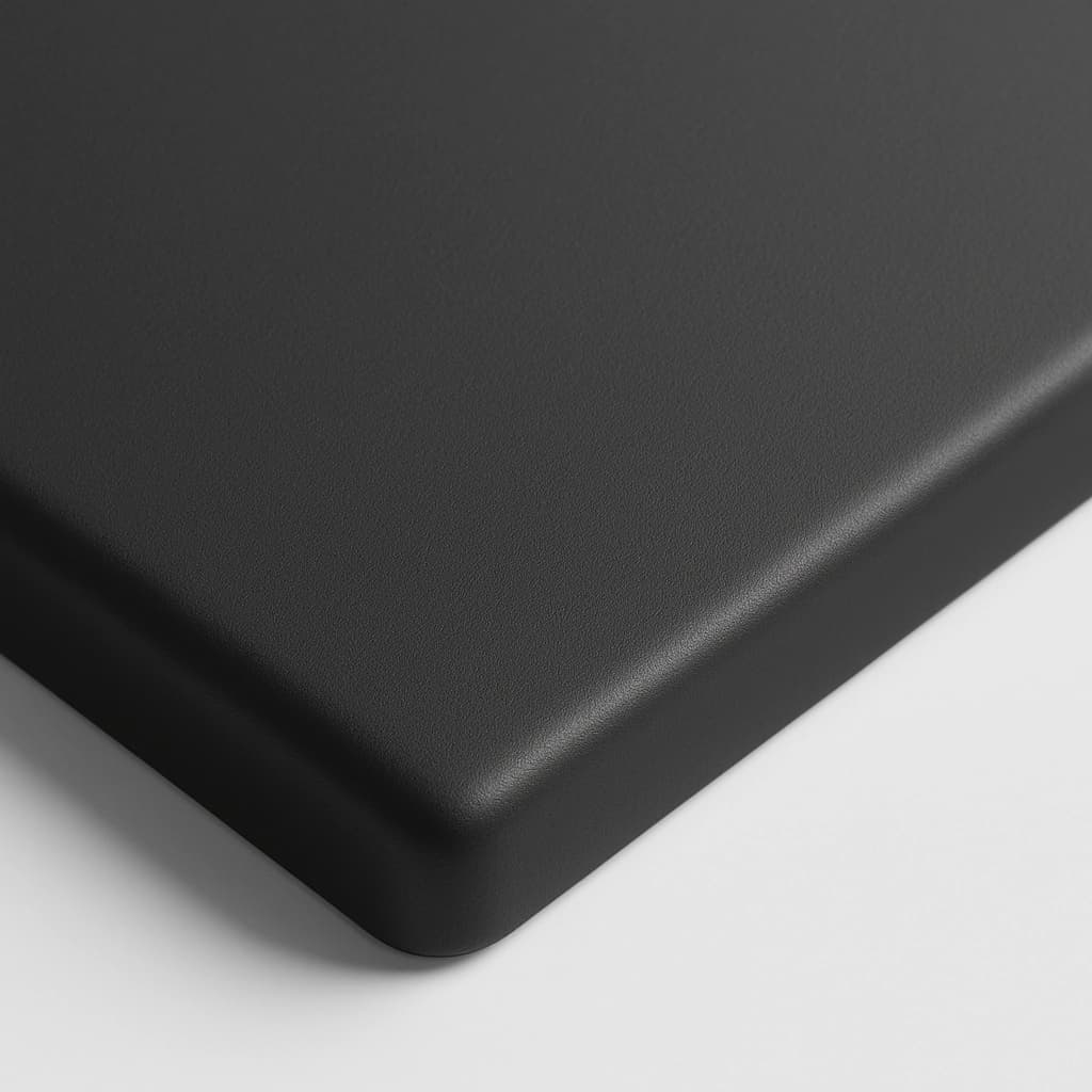
- Atmosphere
- Inert (Argon)